International Journal of Civil Infrastructure (IJCI)
ISSN: 2563-8084

Volume 1 - Year 2018 - Pages 30-41
DOI: 10.11159/ijci.2018.004
Structural Design Developed in a BIM Environment: Benefits and Limitations
Alcinia Zita Sampaio, Vitalino Azevedo
University of Lisbon, Department of Civil Engineering
Av. Rovisco Pais, 1049-001, Lisbon, Portugal
zita@civil.ist.utl.pt; vitalino@ civil.ist.utl.pt
Abstract - In the development of a building design it is important to produce accurate and reliable information, based on a high level of interoperability between systems. It is also necessary to establish good communication between those responsible committed in the project. The main objective of the study consists of a comparative analysis between the traditional process and the Building Information Modelling (BIM) methodology, focusing on the structural component of the project. The study allows the identification of limitations and problems resulting from the analysis of a specific case, and the proposed recommendations and best practices to promote achieving a higher degree of efficiency. Despite interoperability problems verified, the adoption of BIM methodology brings benefits to the Architecture, Engineering and Construction (AEC) sector through technical improvements, reducing the duration of tasks and increasing their efficiency.
Keywords: BIM, Structures, Analyses, Interoperability, Workflow.
© Copyright 2018 Authors This is an Open Access article published under the Creative Commons Attribution License terms. Unrestricted use, distribution, and reproduction in any medium are permitted, provided the original work is properly cited.
Date Received: 2017-11-22
Date Accepted: 2018-05-08
Date Published: 2018-08-28
1. Introduction
Due to the increasing complexity of the construction industry, on design, execution and maintenance, it is mandatory to employ specialized techniques and demand greater efficiency and profitability from contractors and designers. Cooperation and collaboration among the different disciplines of the project is essential to the achievement of a common work, in order to make the process more productive and qualitative, thus obtaining a more efficient building in a competitive and demanding market. Low levels of productivity reported in Architecture, Engineering and Construction (AEC) sector can be understood through the observed fragmentation, explained by the difficulty of introducing new technologies, in which the main mode of communication is based on paper [1], and also, by the fact of construction at the site did not benefit significantly from automation techniques introduced in recent years [2]. The high rates of modifications observed in the early stages of the project, resulting in reconstructions and repairs, affect the overall efficiency of the sector [3] which should accompany the technological, namely automation and modernization, and methodological change, promoting the sharing of information and interdisciplinary communication [4].
The increasing project complexity in the AEC industry, besides boosting the development of methodologies and practices used, stimulates the development of information technologies to support their implementation. The computational systems to support the project, Computer-Aided Design (CAD), are used based only on geometric entities without physical properties and relationship between elements. On the contrary, AEC industry emerging tools, like parametric modelling systems, have the ability to produce parameterized object, with the physical information and the associated relationship, in which the BIM methodology is based. This methodology is characterized by the project execution on a collaborative manner through appropriate working tools, allowing a better understanding of the project and congregating, in a single three-dimensional (3D) digital model and a structured way, all necessary information for project development, construction and building maintenance.
The main objective of this research is a comparative analysis between the traditional process and BIM methodology in the structural design phase. It aims to evaluate the advantages of the adoption and use of BIM methodology, relatively to the usual procedure presents in the AEC industry. Additionally, the present study allows to identify the limitations and to point out the problems that are adhered to the considered study case, allowing defining recommendations regarding procedures and best practices, in order to obtain a higher degree of efficiency in the AEC industry.
The remainder of this work is organised as follows: introduction to BIM concept; identifying BIM workflows Revit/SAP and Revit/Robot; list of a worked-out sequence of processes.
2. Building Information Modelling
BIM is frequently referred at three levels: a software application, a process to design and document information, and also, a new approach to the profession which requires the implementation of new policies, contracts and relationships between the stakeholders [5]. BIM methodology is defined as a modelling technology and an associated set of processes to produce, communicate and analyse models of a building [1]. Succar et. al [6] define BIM as an interactive set of policies, processes and technologies producing a methodology capable of managing key project information and simulate the building in a digital format throughout his entire life cycle. Within a technological perspective, BIM is a project of simulating based on the 3D representation of its components, with a link to the necessary information related to all project phases [7].
It is important to understand the theoretical foundations inherent to this methodology, in order to continue stimulating and developing the technological base, necessary for the implementation and evolution of the BIM process. However, the theoretical BIM concept only acquires practical meaning, by the use of software that admit this integrated methodology, with the most recent information technologies [4]. BIM helps to reallocate the time and effort that designer apply in each project phase, bringing the focus of the effort to the earliest stages of the project, where the value of decisions is more significant, at the level of cost, functionality and benefits. Regarding the design phase, the main objective of the present work, these benefits consist of [2]:
- More precise perception and visualization of project;
- Changes imposed on the BIM model are automatically reflected in corrections;
- Accurate and consistent extraction of 2D drawings at any stage of the project;
- Facilitated collaboration, from the early stages of the project, between different disciplines and stakeholders;
- Better estimation of the enterprise cost during the design phase; and improvement of energy efficiency and sustainability.
The parametric modelling, a basis of BIM methodology, consists of represent objects through parameters and rules that determine its geometry and properties of geometric relationship. The relation parameters allow automatic update regarding the geometry of each object whenever any change is made in the 3D model (change of context). Parametric objects are integrated non-redundant geometric settings, not allowing inconsistencies, and can be customized allowing the modelling of complex shapes. The modelling through parametric objects provides a powerful way to create and adapt model geometry, leading to a modelling process faster and less error-prone, when compared with CAD systems. While in traditional 3D modelling CAD is necessary to manually edit all the geometry of an element, the form and composition of parametric model geometry is automatically adjusted to their context (adjacent elements), based on rules that define it [2].
BIM should be understood as a dynamic process, since the BIM model is built based on the contribution of different teams, supported by BIM tools in performing of their tasks and the transfer of information between them. The BIM model development is a continuous process throughout the building life cycle, characterized by progressive and collaborative elaboration of the design information [3]. The successful implementation of BIM process requires, from the early stages of the project, the involvement of all stakeholders and a correct and efficient communication between them [8].
Interoperability, characterized by the ability of BIM tools exchange and operate building information between them, is a fundamental requirement for communication and collaboration between stakeholders and BIM platforms. It facilitates the workflow of data and its automation, as well as strongly encourages iteration during the design phase [2]. The BuildingSMART organization has developed an open format for representing and exchanging information between AEC software applications, standardized format designated as Industry Foundation Class (IFC) [13]. The universal standard for data exchange models of construction, including geometry, attributes, behaviour and structure of the object, although quite extensive, it still has some limitations, among which the representation of complex geometries [9]. Thus, it is important to continue developing a standardized vocabulary of rules that lead to solving the problems of parametric models interoperability between BIM platforms.
3. BIM Workflow in Structural Design
In the area of shared information, it is common to distinguish between the four stages of BIM which vary between the big BIM and the little BIM and between the individual BIM and the social BIM [18]:
- The social BIM is based on a complete collaborative environment, involving constant exchanges of standardized and controlled information among all stakeholders;
- The individual BIM is related to the processes that occur internally in a company, where there are exchanges of information between different teams implicated in the project;
- Big BIM and little BIM differ in the amount of produced and shared information, whether on internal or social level.
Thus, if BIM is used exclusively from a geometrical perspective, for production of graphic documentation, then the little BIM is applied. When the BIM model is used to explore the basis of information management capabilities, planning, construction and maintenance, the big BIM is involved [19].
This study focuses on the analysis of a lonely big BIM work methodology (within a design company) properly structured to be later integrated in a full BIM collaborative environment. This methodology is shown in Figure 1 and its main feature is presenting how the technical documentation is produced using the parametric BIM model as the central repository of information. The study focuses in a greater detail the structural model generation and the rebar design assessment processes.
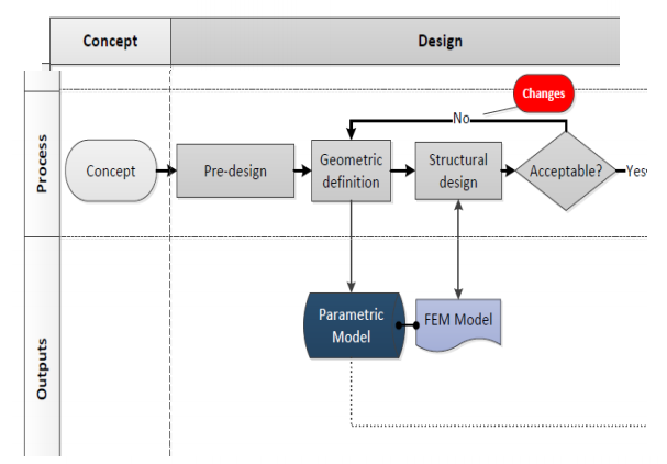
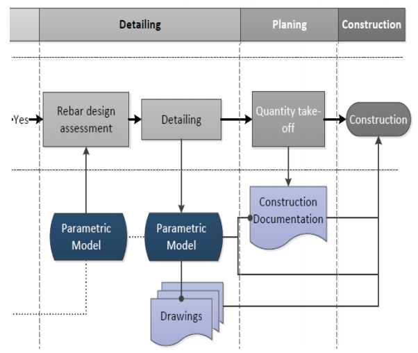
During the structural pre-design stage, it is necessary to collect all the working elements such as the owner’s requirements for the structure or the information of the building’s surrounding characteristics. In a BIM environment, these inputs must be supplied in an electronic form, in order to automatically verify its compliance with the projects characteristics. After the pre-design stage, the next step is the development of the parametric model of the structural solution achieved. Once obtained, the parametric model can be used to automatically create a Finite Element Method (FEM) model. Both models must share a bidirectional link; expressed through the automatic update of one model according to the changes occurred in the other.
With this, it is possible to maintain the typical cyclical process of structural design (using the FEM model) and simultaneously update the parametric model. Sequentially, the parametric model is used for the extraction of drawings, sharing with them a one-way link that guarantees the constant update of the drawn elements. As it can be seen, the proposed BIM methodology generates increases in productivity, while simultaneously improving the quality of the deliverables and the overall project. The proposed work-flow is ideal but the reality still presents many limitations. So this work intends to contribute to the knowledge of the level of interoperability achieved by the BIM-based tools currently in use.
With the development of BIM technology and its increased use in the various phases of the project, it was necessary to create BIM rules which could regulate the modelling process in each country, in an attempt to minimize errors which could arise from the use of various tools. Thus, some countries have adopted the creation of BIM rules:
- The regulation adopted in the United Kingdom, AEC (UK) BIM Protocol [20];
- And those adopted in Singapore, the Singapore BIM Guide [21].
These are considered to be the most complete worldwide, particularly the regulation used in the UK as this is a country which is strict with AEC industry companies in the implementation of the BIM methodology [7]. Just the second international regulation is analysed in the study in order to establish guidelines for the creation of the parametric model.
3.1. First Practical Project
In order to investigate both work-flows and the modelling process, practical case projects were developed. The first selected study case corresponds to a structure of reinforced concrete, showing a distribution of structural elements regular in height, situated in Lisbon, Portugal. The example analysed represents a large majority of the type of existing buildings, and situations studied are those that reflect more common cases. First, using the Revit software, a structural BIM model of the building, was created based on the information provided in AutoCAD drawings of the project. The BIM tool used, the Revit 2015, is very common software which is increasingly being used worldwide. It presents advantages to an experienced user in AutoCAD, since both belong to the same company Autodesk, and have similar interfaces. Another important aspect for the Revit selection is the available interoperability capability with the structural calculation program, Robot Structural Analysis used forward on this work.
3.2. The Modelling Process
The modelling process of a structure, using a BIM-based tool, requires the designer to know the abilities of the BIM system which are available for the generation of the structures´ model, so as to establish the required structural solution. The model created must contain the information necessary to the automatic achievement of the structural analyses, project drawings and bills of quantities. But it is necessary that the engineer knows in detail the process of modelling and its limitations so that he can be accurately critic of the modelling of the achieved analytical structure. It is also required that the designer understands the means of communication between computational systems of modelling and calculation. The designer should carefully analyse the process of the information transfer between systems and how the interpretation of the structural elements of the model is made.
The sequence of the modelling made was: grid alignments and structural levels, vertical elements, beams, slabs and foundations. In the stage preceding the project it is necessary to collect the aspects referring the material to be used associated to its physical and mechanical characteristics. Revit has the ability to make each modelled structural element as an analytical element. It interprets as linear FEM elements the columns and beams; and as surface FEM elements the walls and slabs. The program automatically makes some approximation at the analytical model level. There are, however, some approximations that must be manually made on Revit, so that the analytical model can be used for the structural calculation.
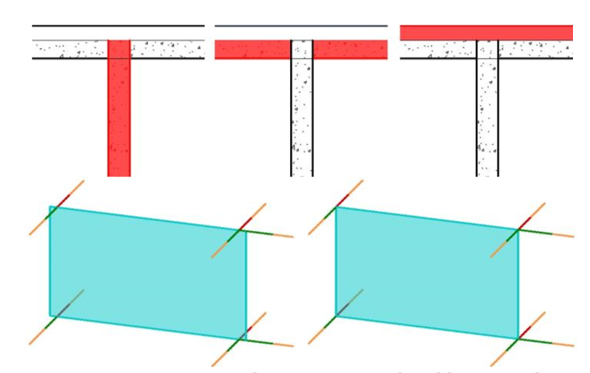
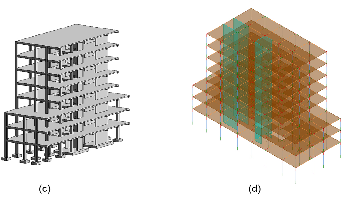
In the modelling process of structural elements the document Singapore BIM Guide was taken into consideration. Accordingly, the vertical elements were modelled by level, so as to safeguard the aspects related to the slenderness ratio of the elements. The beams were modelled span to span to satisfy criteria for unsupported length in the analytical models. In this context the relationship between vertical elements and beams were analysed for the purpose of volumetric calculation. Figure 2 illustrates the type of interaction obtained, shown in red, of the vertical element, the beams and the slab. But, this type of modelling and understanding of the program implies that the volume of the concrete is not in accordance with the constructive phasing, although it shows the correct total values. Considering the construction planning of the building it is then required to introduce some changes accordingly.
The third stage of the study is the verification of the analytical model which is the base of the structural calculation. The creation of the analytical model shows some inconsistencies and it is therefore necessary to make some corrections, so as to obtain a reliable model for the structural calculation.
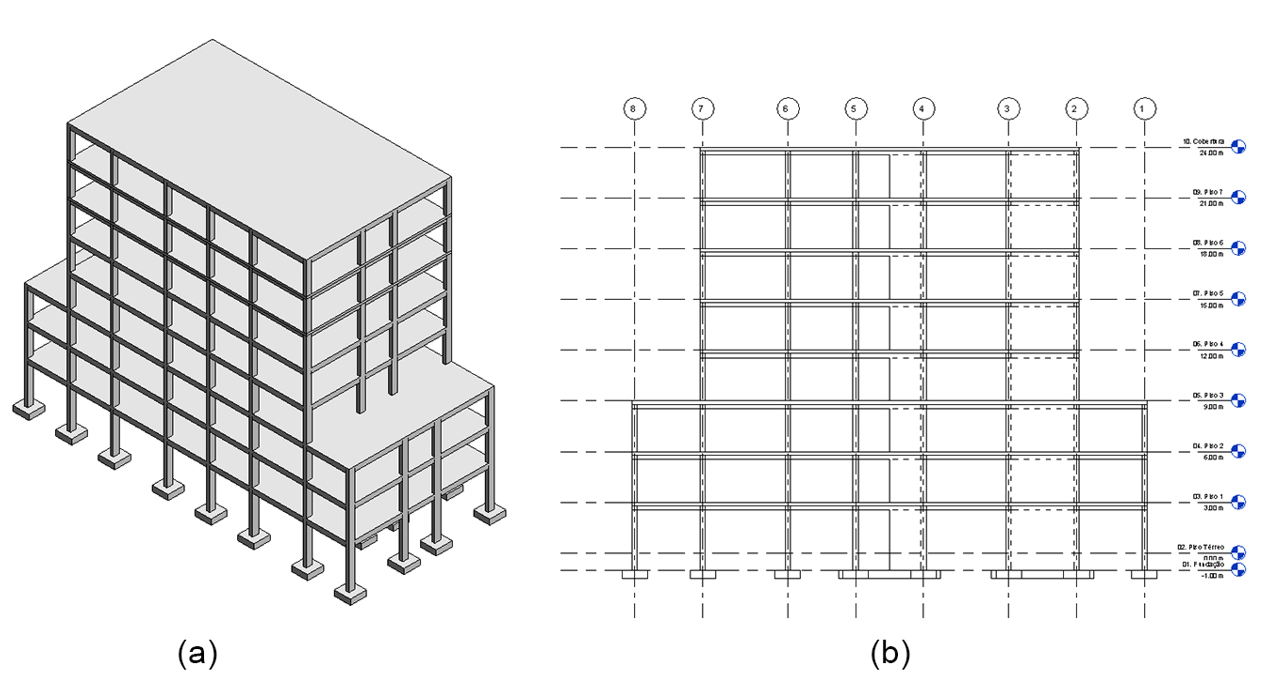
The situation whereby the analytical element which represents the wall, shell element, and which should end up on a vertical plan of the axis of the beams which are perpendicular to the wall, exceeds that limit and this was corrected (Figure 2). Figure 3 shows the final geometrical model represented as a projected axonometric perspective and as a vertical section. The figure contains also the analytical model resulting from the established structural solution.
3.3. Transposition Revit/Robot and Robot/Revit
The transfer of information between the modelling program (Revit) and the calculation program (Robot), occurred with no difficulties. Some adjustments were introduced in the Robot model: stairs elements were modelled as sloped slabs, in order to be considered its effect on the pillars adjacent to stairs; the moment of inertia in beams was reducing in 50% according to the y and x axes, in order to consider the cracking of concrete; it was considered that the effect of torsion in beam and column is negligible. Figure 4 shows the model with the patterned stairs. After these changes the analytical model is prepared to perform analysis under the action of normalized load situations. The normal structural analyses take then place and the results are transferred to the Revit software.
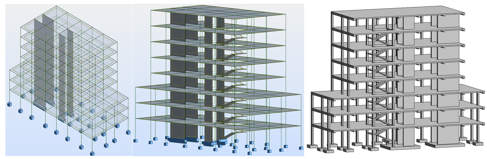
In the reverse transposition, from Robot to Revit, when updating the Revit model, there are mistakes in the model, namely, new structural elements appear, which should not be accepted in the model. Figure 4 shows the updated model, where the stairs are shown, which was not shown in the original model. At the bottom of the stairs a footing divided in its finite elements, is now shown. It was decided not to update the model thus avoiding possible mistakes made from the updating using the Robot model as shown on the example given. It also allows a better control over the detail of the reinforcement.
3.4. Rebar Detailing and Bills of Quantities
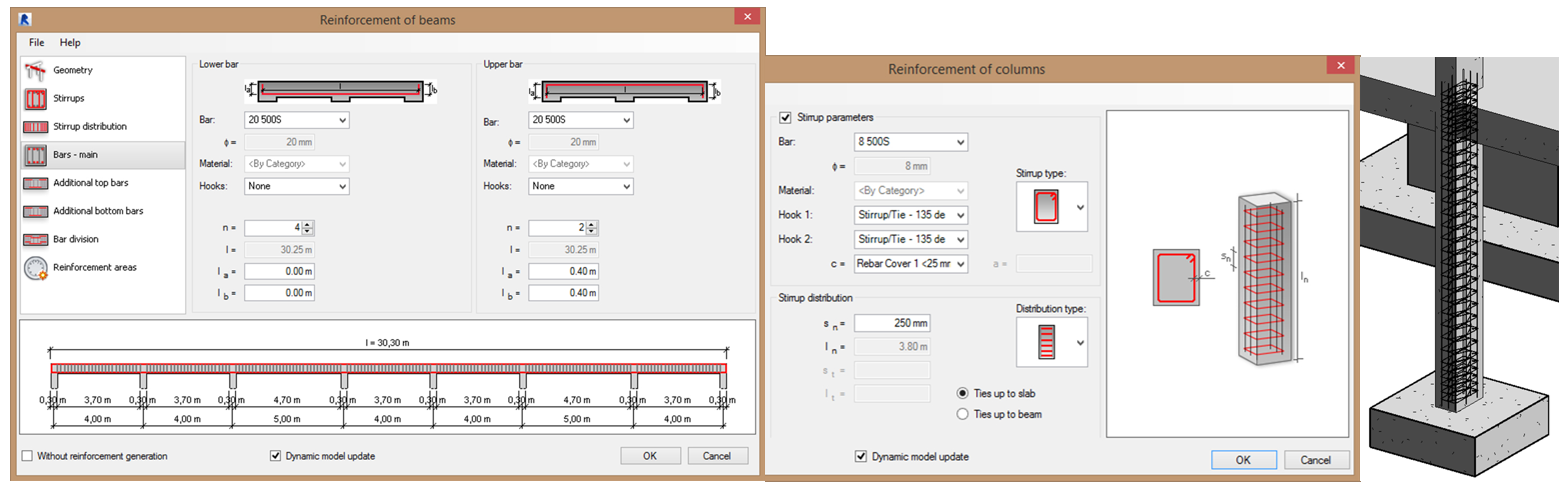
An analysis was made to the capacities of the BIM tool used for the detailing of the reinforcement, using an extension of the program Revit Extensions. This extension allows the insertion of the reinforcement in the concrete, in a more intuitive and faster manner. It was observed, as a result of this analysis, that there is no execution compatibility between what is usually made in structural projects and what the program allows.
There were difficulties in this process, namely, in the detailing of the structural beams where the program considers the insertion of the reinforcement in accordance with the modelling made. So, as the beams where modelled span to span, the reinforcement is introduced per span, and there is no continuity in the beam with N spans. The difficulty in detailing can be solved by using tools dedicated to this type of situation, such as AutoCAD Structural Detailing (Figure 5). This software can be linked to Revit and allows the detailed manipulation of the different drawings.
The analytical model and the flux of information between Revit and the Robot structural calculation system is analysed in both directions. At the end of this analysis, the inclusion of reinforcement in the concrete elements is made, with the purpose of obtaining the correct structural drawings. One of the aspects of the BIM methodology is the ability to obtain information from the parametric models that were created. Using the tools available from Revit, it was possible to obtain, in a swift manner, the tables referring to the concrete volume (Figure 6) and the quantity of reinforcement.
The values were confirmed manually, thus confirming the ability to obtain accurate information from the model. Bills of quantities were obtained which can be used for budgeting.
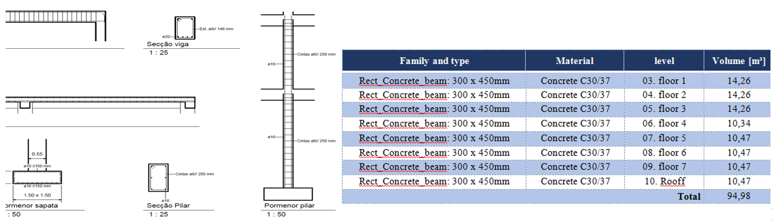
The analysis was completed by explaining how to obtain drawings to be able to move on to the next stage of the project. Drawings were thus created in an intuitive manner, using tools available from Revit, and which show a high capacity to organize the drawings (Figure 6).
4. Traditional Process
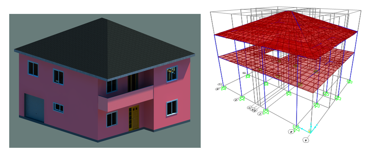
In this work was selected, for modelling example, a two-storey building located in northern Portugal. The creation of the Revit architecture model (Figure 7, left) based on architectural drawings provided in paper format, was performed using a BIM base software (BIM platform), Revit 2013 developed by Autodesk [14].
The modelling process is based on parametric objects (parametric modelling) with well-defined parameters and characteristics which require previous knowledge and definition of the composition and properties of the object elements. This invariably involves customization and standardization of Revit according to the project in question [10]. Frequently this aspect is mentioned as restrictive to the adoption of BIM, because is required a significant investment of time collecting information and formatting it.
The structural solution was defined based on the architecture model and the options considered are consistent with a sufficiently complete structural design to perform the comparison between the traditional process, without a direct transposition of structural elements, and the one presented by BIM.
The preliminary design of the structural elements geometry was carried out based on the architectural constraints of the building, the imposed actions, and the used materials. With this information and using the Structural Analysis Program 2000 v15.1.0 (SAP2000) software, developed by Computers & Structures Inc (CSI), proceeds to the modelling of the building structural elements reaching the SAP2000 model (Figure 7, right). The structural design made according to this methodology does not include any form of interoperability for structural elements (with format recognition) between the applied software, and therefore, requires manual data entry without information transfer. Finally, based on the stresses in the structure, the amount of steel to be used in reinforced concrete elements was determined through present regulations.
5. Information Workflow between Revit and SAP2000
This item discusses the ability of interoperability between Revit and SAP2000 platforms, where essentially, is tested the transposition of the Revit structural model for SAP2000. In this process is analysed the type of information that is maintained or amended, and which adaptations are necessary make on obtaining an effective and correct SAP2000 model. The transposition of data between the Revit geometric model and the SAP2000 model is conducted only in one direction, not allowing subsequent updates.
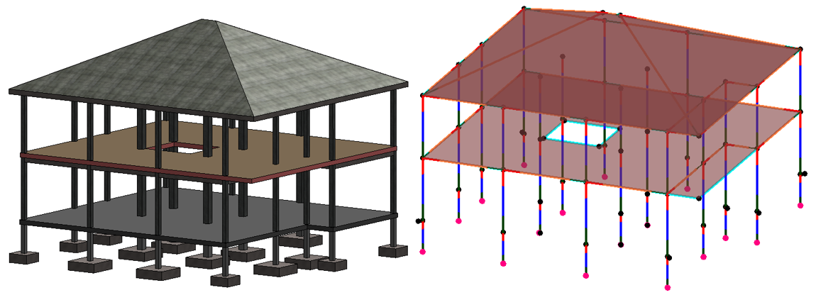
The structural model is defined resorting to the Revit Structure component. In its definition is considered the preliminary design where the dimensions of the building structural elements were established. Thus, the structural solution and dimensions adopted are similar as the ones used in the SAP2000 model conception according to the traditional procedure. By the fact of the structural elements available in Revit Structure are equally parametric objects, it was necessary to characterize them setting its parameters before the construction of the Revit structural model (Figure 8, left).
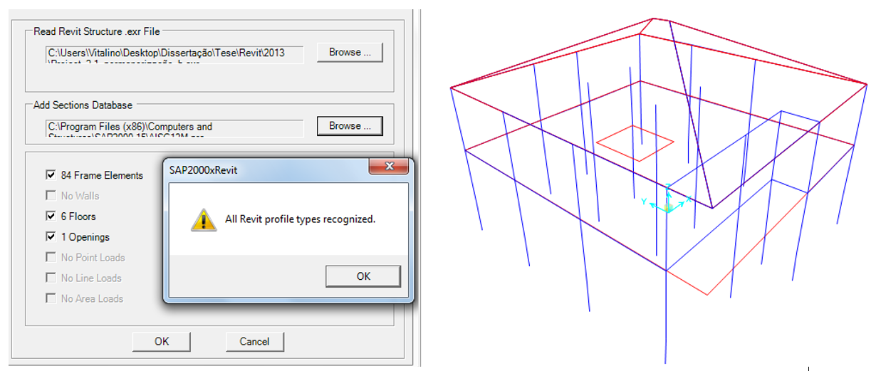
The Revit structural model, constituted only by structural objects and alignments (grids), is transferred to SAP2000 trough CSIXRevit 2013 plug-in, also provided by CSI. When the model is imported into SAP2000, there is a correspondence between the section type designation of the bar elements and the SAP2000 database (.PRO files) [11]. Therefore, it was necessary to modify these files in order to contain the section type designations corresponding to those importing into SAP2000.
This operation is performed through the Visual Basic for Applications (VBA) programming macro contained in the proper.xls Excel file, supplied by CSI [15]. The import interface of Revit structural model (left) and the final result of the SAP2000 model imported (right) are shown in Figure 9 As can be seen, this model needs to be completed so as to be identical to that determined by the traditional method (Figure 7, right).
Although this information workflow cannot be described as the ideal methodology, taking into account constraints that condition the efficiency of BIM model, it has significant advantages compared with the traditional process. Therefore, it was possible to illustrate what at the moment is transverse to the AEC industry, an evolution from the traditional process towards the BIM methodology.
In conclusion, the main advantages are listed:
- Decrease of the amount of errors and inconsistencies in the structural design;
- Decrease of the total project duration;
- Increase of the overall efficiency.
As well as the limitations encountered in this process: - Unidirectional information workflow (updates not supported);
- Limitations on the type of elements transferred;
- Difficulty in transposing slabs openings;
- Inability to transfer alignments (grids);
- Failure to recognize the constraints of foundations.
6. Information Workflow between Revit and Robot
This item analyses the ability of interoperability between Revit and Robot Structural Analysis Professional 2013 (Robot) software. Initially, the Revit structural model, created in the previous item, was exported to Robot. Here is performed the analysis and stress calculation of the structure and the reinforcement design. Then, the detail drawings are exported to AutoCAD Structural Detailing 2013 (ASD) software with the aim of improving its definition realized in Robot. Both software products also belong to Autodesk, therefore is expected that the results, in terms of interoperability capacity, to be quite acceptable. The data transfer between Revit and Robot facilitates the coordination of geometric information (architectural model, structural model, etc.) with analytical information. The Revit structural model (Figure 8, left) created associates the geometric component of the structural elements (slabs, columns, etc.) to an analytical model (Figure 8, right), information that is incorporated into Robot in order to perform the stress analysis and the structural design [12].
The data workflow between Revit and Robot can be performed in both directions, allowing multiple iterations and updates, although a few parametric objects cannot be transferred with an acceptable effectiveness. However, in this aspect, there is a great improvement compared to the previous workflow [12] [16]. Before exporting the analytical model is necessary to proceed to its validation, to which Revit has specific tools, in terms of static coherence between the various elements, in particular, their connections and boundary conditions [17].
After the validation of the analytical model, proceeds to the export through the Integration with Robot Structural Analysis Extension, taking into account the definition of the given options:
- The type of load, load case, which accounts for the self-weight;
- The degrees of freedom of the bar elements;
- The used materials; among others.
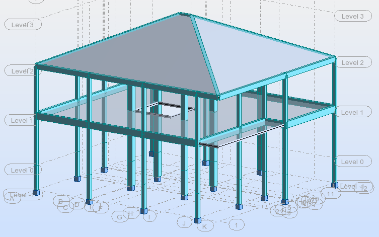
After defining the load combinations, the stiffness of the bar elements, and finite element meshes, are determined the stresses in the structure. During the progression of the project, and taking into account possible divergences in the collaboration of several teams, it is necessary to consider an appropriate organization with an appropriate hierarchical structure for decisions regarding the management of BIM model [12]. The Robot structural model (Figure 10) continues to be organized and constituted on an ongoing process of information workflow between Revit and Robot.
The next step was to determine the amounts of steel that verifies the safety of the calculated elements. The Reinforcement of RC Elements tool, existent in Robot, performs the calculation of the necessary amount of steel based on the considered regulation (EC2 e EC8), and also generates the detail drawings of concrete reinforcement elements. This tool, despite the necessary cautious in its use, can be considered a support tool of the BIM process. Essentially, it is responsible for creating new information from existing one, helping to enrich and facilitate the management and execution of the project. This information besides the graphical component, based on the detail drawings (Figure 11), also contemplates a descriptive component which stores all the design information of each structural element.
Due to the fact of detail drawings created in Robot, in some cases, do not fulfil the user requirements; it was found another more interactive and versatile manner to define them.
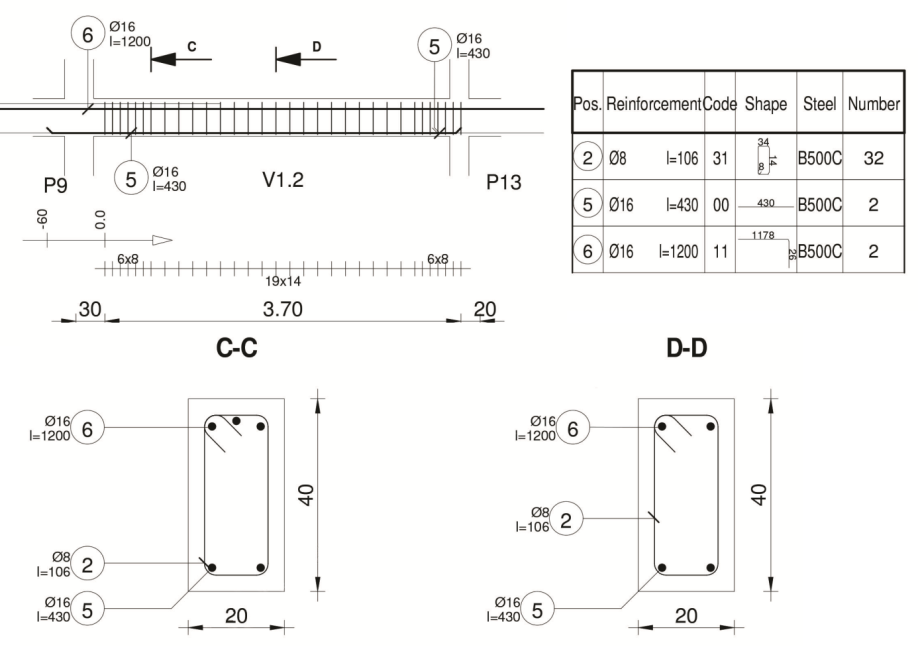
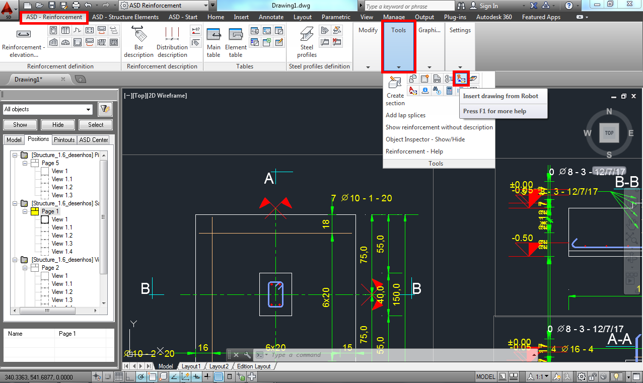
The objective is to give him more control in the options taken regarding the detail drawings. Accordingly to this, these drawings were exported to ASD (Figure 12) and de necessary adjustments were made in order to complete them.
Based on the tests performed, it has been found that the inclusion of ASD in the data workflow between systems contributes to an improvement in the overall quality of graphical information, due the high degree of customization given to the user. However, in this study, it was inconclusive which choice is more fast and effective for the development of this task, given that much will depend on the desired end goal for the layout of each concrete element.
Since the time factor is an important variable to consider in a project, use the drawings made in Robot may prove to be decisive. Ultimately, the dimension of the project, the type of structural elements and the professionals themselves will affect this selection. We conclude by comparing this information workflow with the previous, that the advantages checked there, were overcome with enhanced quality and efficiency levels, and the limitations were globally suppressed.
7. Discussion
The focus of this work consisted basically in the comparison between the traditional process of the structural design execution and the one recommended by BIM methodology. Three different approaches for implementing structural design were analysed:
- Traditional process (without information transfer, no data workflow);
- BIM with data workflow between Revit and SAP2000;
- BIM with data workflow between Revit, Robot and ASD.
It was possible to determine the advantages and limitations of BIM methodology over the traditional process in this project phase. Additionally, with the characterization of two different information workflows - resorting to the use of different platforms and tools – was verified the existence of deficiencies at interoperability level in BIM methodology. Consequently, there still is a long road ahead in order to obtain an efficient interoperability between the currently existent software on the market. The traditional process has obvious deficiencies and disadvantages identified in the tests realized, especially with respect to the data workflow between Revit, Robot and ASD:
- Semi-manual coordination of structural and architecture models;
- Manual coordination of model changes;
- Manual construction of detail drawings of the reinforced concrete elements;
- Manual obtaining of quantity take-off and cost estimating
Regarding the BIM methodologies analysed, were observed significant differences in the achievement of the proposed objectives. A unidirectional link between Revit and SAP2000 revealed some disabilities that affect the efficiency and overall quality of the project, namely, the inability to update the BIM model with the design information and the own effectiveness of this information transposition. On the contrary, the link with Robot supports bidirectional workflow, the update of the BIM model information, and the transposition of parametric objects was performed with a high degree of effectiveness. This difference in the interoperability quality is justified mainly by the fact that these software products are developed by the same manufacturer.
From the results of the work carried out, it can be concluded that, the BIM workflow of information more recommended consists in:
- Modelling of the structural elements and analytical model configuration in Revit;
- Definition of actions, calculation and stress analysis, and structural elements design in Robot;
- Finally, drawing detailing and composition of steel and concrete quantity take-off in ASD.
With the selection of SAP2000 software (data workflow with visible deficiencies) was demonstrated the occurrence of several difficulties in the implementation of BIM methodology in certain cases, within the AEC industry. Therefore, it is important to manage the level of expectations created among all stakeholders in order to decrease the amount of dropouts in early stages of the BIM methodology adoption.
8. Conclusions
Building Information Modelling (BIM) is a concept that has been spreading throughout the Civil Engineering industry at a large scale. However, the adoption of BIM introduces new capabilities into the work-flows of the companies in the Civil Engineering sector. The present work approaches the BIM methodologies, directed to the structural design stage of the project lifecycle. Therefore, in order to establish a proper work base, the study analysed two BIM work-flows: modelling and reinforcement detail performed in Revit and modelling in Revit and define the reinforcement detail in Robot. These work-flow performances were applied in two practical cases in order to validate both sequences of BIM work and to identify advantages and limitations of its implementation
It can be concluded that a major contribution of BIM methodology lies in the automation of performed tasks, which, in the traditional process, are executed manually increasing considerably the quantity of errors and project inconsistencies. Direct and immediate consequences are the reduction of the time variable associated to the design phase and the increased of its quality. This brings the decrease of the enterprise total cost, becoming the sector more competitive and transparent. It is an important conclusion to the extent that BIM methodology besides contributes to improving the effectiveness of the AEC industry, provides the increasing of their efficiency levels.
References
[1] B. Becerik-Gerber and K. Kensek “Building Information Modeling in Architecture, Engineering, and Construction: Emerging Research Directions and Trends,” Journal of Professional Issues in Engineering Education and Practice, vol. 136, pp. 139–147, 2010 View Article
[2] C. Eastman, P. Teicholz, R. Sacks and K. Liston, BIM handbook: a guide to building information modeling for owners, managers, designers, engineers and contractors. New Jersey, EUA: John Wiley & Sons, 2011.
[3] A. Grilo and R. Jardim-Gonçalves, “Value proposition on interoperability of BIM and collaborative working environments,” Automation in Construction, vol. 19, pp. 522-530, 2010. View Article
[4] J. Lino, M. Azenha and P. Lourenço, Integração da Metodologia BIM na Engenharia de Estruturas. Porto: Encontro Nacional Betão estrutural, 2012.
[5] G. Aranda-Mena, J. Crawford, A. Chevez and T. Froese, “Building Information Modeling: Does it Make Business Sense to Adopt BIM?,” International Conference on Information Technology in Construction, Santiago, Chile, 2008.
[6] B. Succar, W. Sher and G. Aranda-Mena, “A proposed framework to investigate building information modeling through knowledge elicitation and visual models,” Conference Proceedings of the Australasian Universities Building Education Association, Melbourne, Australia, 2007.
[7] W. Kymmell, Building Information Modeling: Planning and Managing Projects with 4D CAD and Simulations. New York, USA: McGraw Hill Construction, (2008).
[8] R. Crotty, The Impact of Building Information Modelling. Transforming Construction SPON Press, 2011.
[9] C. Eastman, S. Jeong, R. Sacks and I. Kaner, “Exchange Model and Exchange Object Concepts for Implementation of National BIM Standards,” Journal of Computing in Civil Engineering, vol. 24, no 1, pp. 25-34, 2010. View Article
[10] P. Davis, C. Busa, M. Taurer, S. Stafford and A. Mcdonnell, Introducing Revit Architecture 2013. John Wiley & Sons, Indiana, USA, 2012.
[11] Computers and Structures, Inc., CSIXRevit - SAP2000®, ETABS® and Revit® Structure -2009/2010/2011/2012. Data Exchange Documentation. California, USA, 2011.
[12] Autodesk, Integrating Revit Structure and Robot Structural Analysis Professional. California, USA, 2012.
[13] BuildingSMART. [Online]. Available: http://www.buildingsmart.org/ [January 2017].
[14] Engineering News-Record (ENR). [Online]. Available: http://enr.construction.com [August 2017].
[15] ConstruAprende. [Online]. Available: http://www.construaprende.com/foros/personalizacio n-sap-2000-vt2128.html [August 2017].
[16] Autodesk Revit Structure Blog [Online]. Available: http://revitstructureblog.wordpress.com [December 2016].
[17] Revit & Robot Inside Blog. [Online]. Available: http://inside-revitrobot.blogspot.pt/2012/11/ligacaoentre-o-revit-e-o-robot.html [August 2017].
[18] F. Jernigan, Big BIM little BIM: the practical approach to building information modeling - integrated practice done the right way, 2nd ed. AIA, 4SitePress, 2007, ISBN-13: 978-0979569920, ISBN10: 0979569923.
[19] P. Serra, “Analysis of the implementation of BIM processes applied to the structural design,” M.S. Thesis in civil engineering structures, University of Lisbon, Portugal, 2015. [Online]. Available: https://fenix.tecnico.ulisboa.pt/departamentos/decivil /dissertacao/565303595500162 [July, 2016]
[20] AEC (UK) BIM Technology Protocol v2.1, Practical implementation of BIM for the UK Architectural, Engineering, and Construction (AEC) industry, 2015. [Online]. Available: https://aecuk.wordpress.com/documents/
[21] BIM-SG, Singapore BIM Guide, 2012. [Online]. Available: http://bimsg.org/bim-guide/sbg/