International Journal of Civil Infrastructure (IJCI)
ISSN: 2563-8084

Volume 2 - Year 2019- Pages 1-17
DOI: 10.11159/ijci.2019.001
Study on the Effect of Different Bed Sills on Flow Structure and Scouring At the Bed of Channel
Alireza Keshavarzi1,2, Moslem sohrabi2, Bijan Samali1
1Centre for Infrastructure Engineering, Western Sydney University
Penrith, 2747, Australia
A.Keshavarzy@westernsydney.edu.au; B.Samali@westernsydney.edu.au
2Water Engineering Department, Shiraz University
Shiraz, Iran, 71444
Moslem.sohrabi@gmail.com
Abstract - Stabilizing the banks and bed of the river is one of the most important problems in river engineering. This importance arises from the scouring of the banks and bed of a river impacting on hydraulic structures and the aquatic environment. In this study, both experimental and numerical techniques were employed to analyse concave, convex and sine bed sills. It was found that in concave bed sill vortices develop at the banks and transfer sediment particles to the middle of the channel, conversely in a convex bed sill vortices develop at the centreline and move sediment to the banks. The experimental results also confirmed that the maximum scouring depth occurred at locations where vortices develop for the concave and convex bed sills. This caused stability of the channel centreline for concave bed sill when compared to the convex bed sill. Result for convex bed sill showed stabilization at the banks by creating minimum depth of scouring at the banks of the channel. Since both concave and convex bed sills stabilize bed at centreline or banks only, a sine bed sill is also proposed in this study to protect both banks and centreline. The sine shape bed sill was also tested in this study and the results showed that it is very effective for the stability of both centreline and banks.
Keywords: River engineering, Bed sills, Scour, Experimental model, Numerical model.
© Copyright 2019 Authors - This is an Open Access article published under the Creative Commons Attribution License terms. Unrestricted use, distribution, and reproduction in any medium are permitted, provided the original work is properly cited.
Date Received: 07-17-2018
Date Accepted: 10-12-2018
Date Published: 06-09-2019
1. Introduction
River bed stability is not the only a problem in river management but also a creation of riverine habitat for fishes and aquatic ecosystem. Consequently, recent river restoration techniques have developed as important environmental protection to prevent scouring or to exclude sediment from the water [11, 12, 18, 25]. Bed and bank erosion is a common cause of river form. It is due to the flow variation in the river channel particularly during flood events. When flow just overtops the main channel, the dominant flow causes a change in river pattern [4, 10]. Protecting the bed and banks of river against changes requires a river management plan and a designed river training mechanism. The bed of the river is very susceptible to erosion due to high shear stress at the bed particularly around bridge piers [14, 15, 16, 19, 21], therefore improved protection of bed river is essential. To alleviate this, training works must be carried out to decrease the possibility of bed erosion.
The most beneficial solution to confront the problem of scouring at the bed is using bed sills. Some studies by [1] and [17] have shown that bed scouring downstream of a rectilinear sill in a hydraulic jump creates maximum scouring hole at the downstream of the rectilinear bed sill. They showed that at equilibrium condition, turbulence intensity was very high in the scouring hole and they proposed two equations for estimation of maximum scouring depth. The maximum scour downstream of large hydraulic structures in rivers was measured [22, 23]. Some studies by [2], [5], [7], [8] and [24] have also shown bed scouring around rectilinear bed sill that constructed at right angle to the flow direction under different flow conditions. In the above studies it was found that a consistent scouring depth created transversely at downstream of a rectilinear bed sill. Additionally, in a work by [3], the scouring at downstream of multiple bed sills with different horizontal distances have been studied and finally proposed a non-linear regression relationship to determine maximum depth of scouring.
An experiment study showed that bed scouring downstream of rectilinear bed sill with different distances and under steep bed slope exhibited a non-linear regression relationship from which maximum depth of scouring could be determined [9]. In a comprehensive experimental program, the scouring hole around different types of bed sills was tested and concluded that concave bed sill produced minimum bed scouring at the centre of the channel whereas convex bed sill produced minimum bed scouring occurred at the banks [11]. Their results were verified by testing nine different models of bed sills including rectilinear, convex, concave and tilted fixed to the flow direction. Some studies by [13, 20] have shown the impact of shape and adjustment of bed sills on the bed and bank scouring at the downstream of the bed sills. The measurement of bed scouring at the downstream of bed sills showed that the maximum amount of scouring at the banks of the channel occurred by concave bed sill whereas the convex bed sill had the maximum amount of scouring at the centreline of the channel. Furthermore, the stabilization at the bank and at the centre of channel observed at the downstream of butterfly, wing shape and sine bed sills. The location of maximum depth of scouring depends on their shapes and adjustments.
The pattern of flow and turbulence structures in a scour hole downstream of a submerged weir was examined also by [6]. The results showed that flow structure changed near the structure at downstream of submerged weir, where a large vortex area and flow reattachment area were formed. The above study showed that flow regimes over the weir were independent of the sediment size at the bed, and also flow regime could be defined as a function of upstream Froude number and weir height to tail water depth ratio.
With regard to the complication of flow structure around each type of bed sill, it is essential to focus on both experimental and numerical analysis of flow structure in order to assess the flow patterns and their influences on the bed and the banks of channel. Accordingly, a comprehensive research program has been done in an erodible bed to evaluate the flow structure at downstream of different bed sills.
2. Materials and Methods
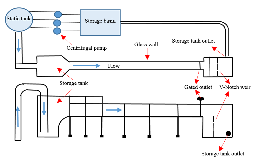
A set of experimental tests were undertaken in a non-recirculating mobile bed glass flume with length, width and depth of 15 m, 0.7 m and 0.6 m, respectively (Figure 1). The length of test section was 3 m and was located 7 m from the inlet. The bed of the flume was covered with 120 mm uniform sand particle with D5 0 equals to 0.78 mm (CU =1.42 and Cc= 0.97). Figure 2 shows grain size distribution of bed material used in this study. Table 1 shows the flow conditions for data set of experiments. Figure 3 demonstrates the three different types of bed sills. These three types include, concave, convex and sine shaped bed sills. These bed sills were installed at the bed of flume to inquire the influence of each type on erosion of the bed and the banks of the channel. Each experiment was operated for about 18 to 24 hours to achieve equilibrium condition. Moreover, a digital roughness meter was used to measure the bed scouring in a grid. The water depth inside the flume was controlled by a gate at the end of the flume. Furthermore, measurement of the flow rate and velocity were made by a pre-calibrated V-Notch and Micro-ADV, respectively.
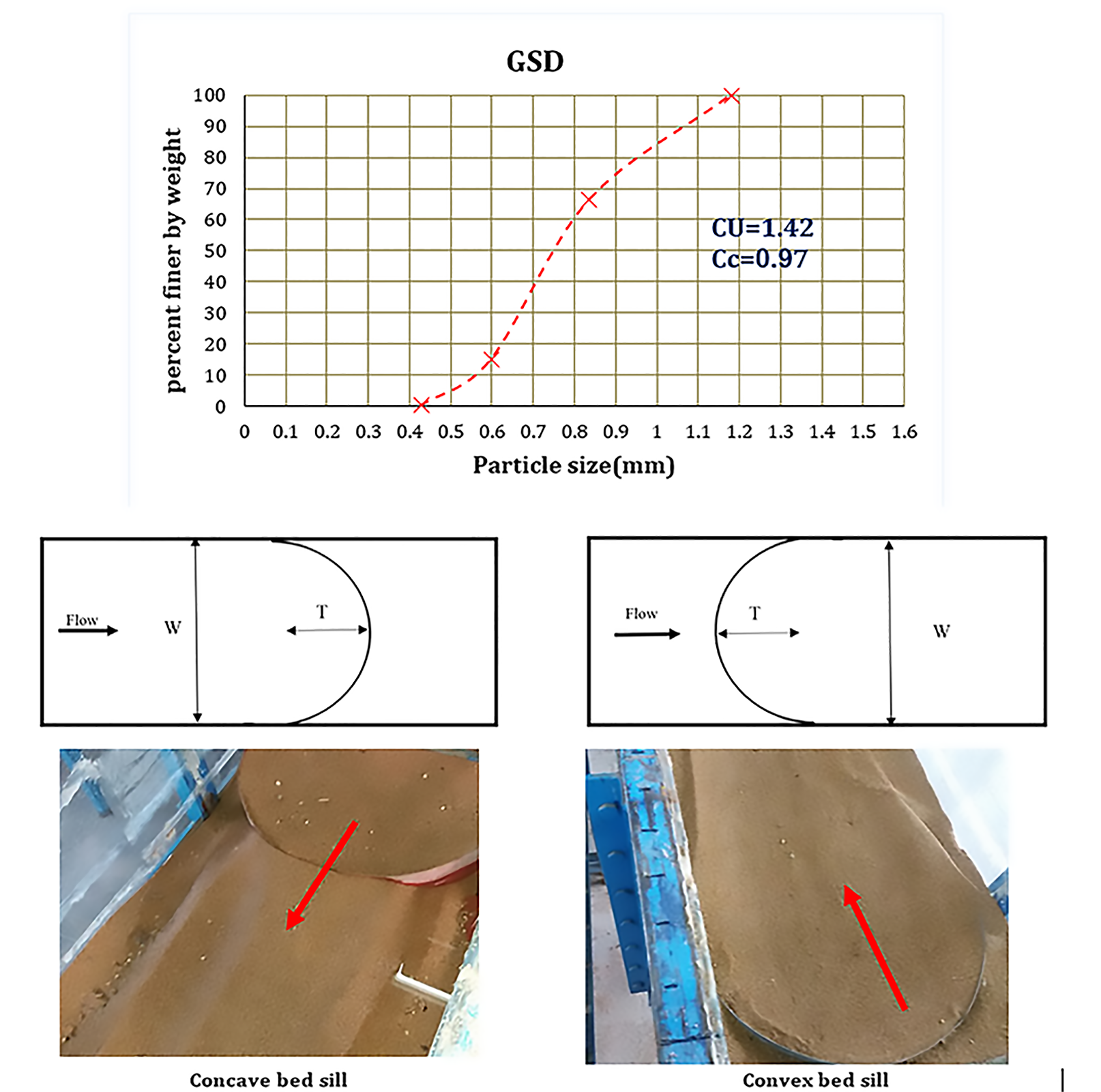
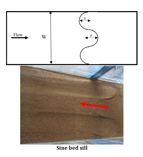
Table 1. Flow condition in the experimental tests, maximum scouring, cells and errors.
| Model | Flow depth(m) | Flow depth(m) | Cells | Zs (m) |
| Concave(M) T=0.25 | 0.06 | 0.32 | 299003 | 0.094 |
| Convex(N) T=0.25 | 0.07 | 0.26 | 221790 | 0.052 |
| Sine(A) E=1P=1 | 0.073 | 0.30 | 286666 | 0.083 |
3. Experimental Results
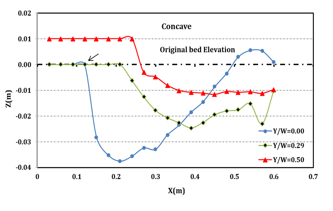
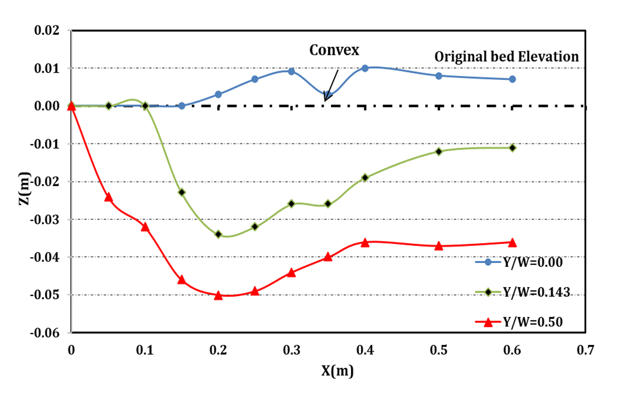
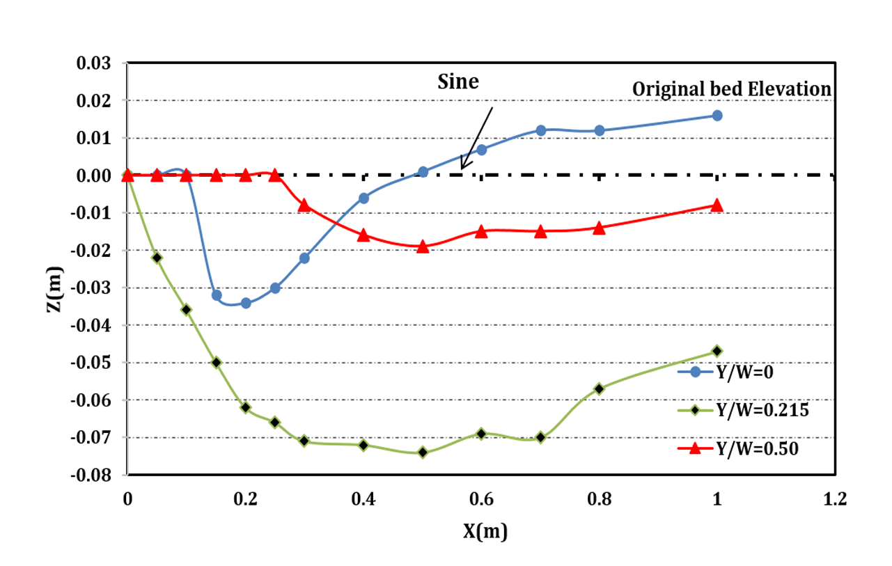
The concave bed sill is shown to be effective in reducing the erosion at upstream and to stabilize the central section downstream of the bed sill. Therefore, use of concave bed sill has led to the formation of scouring hole at the banks of the channel. In addition, the scoured bed profiles at Y/W=0.5, 0.29, 0 are shown in Figure 4a for concave bed sill. Figure 4a confirms that the maximum scouring depth occurs at the banks of the channel while the channel centreline has the minimum scouring depth. However, the convex bed sill showed an opposite and very different result (see Figure 4b). The profile of convex bed sill at distance Y/W=0.5, 0.143, 0 from the wall is presented in figure 4b. Figure 4b shows that the maximum scouring depth occurred at the centre of the channel. It can be observed that the middle part of the channel with convex bed sill has a maximum scouring depth. By moving away from the banks of the channel, the depth of scouring increases. It is mostly recommended for protection of upstream and banks at downstream of the bed sill. Furthermore, the convex bed sill makes an aquatic habitat at its downstream. As mentioned above, the use of concave or convex bed sill may stabilize either centre or banks of a channel. Nonetheless, a combination of concave and convex bed sills referred to as sine bed sill may help to protect both centre and bank of the channel. A sine bed sill is a concave bed sill surrounded by two convex bed sills at the sides as it is shown in figure 3. The results of scouring profile for Y/W=0.5, 0.215, 0 for sine bed sill are presented in Figure 4c. It is obvious that the max scouring depth is located at 0.15 meters interval from the walls.
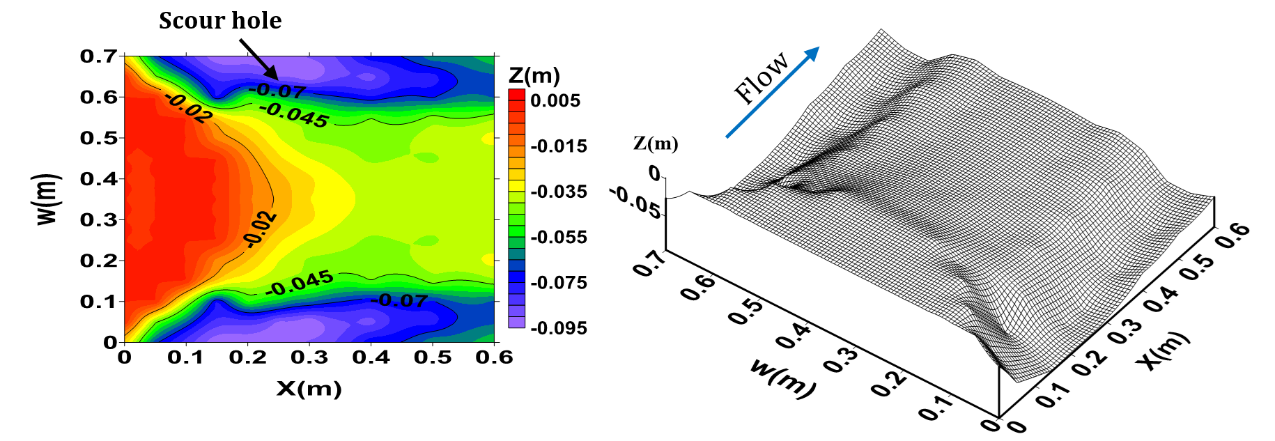
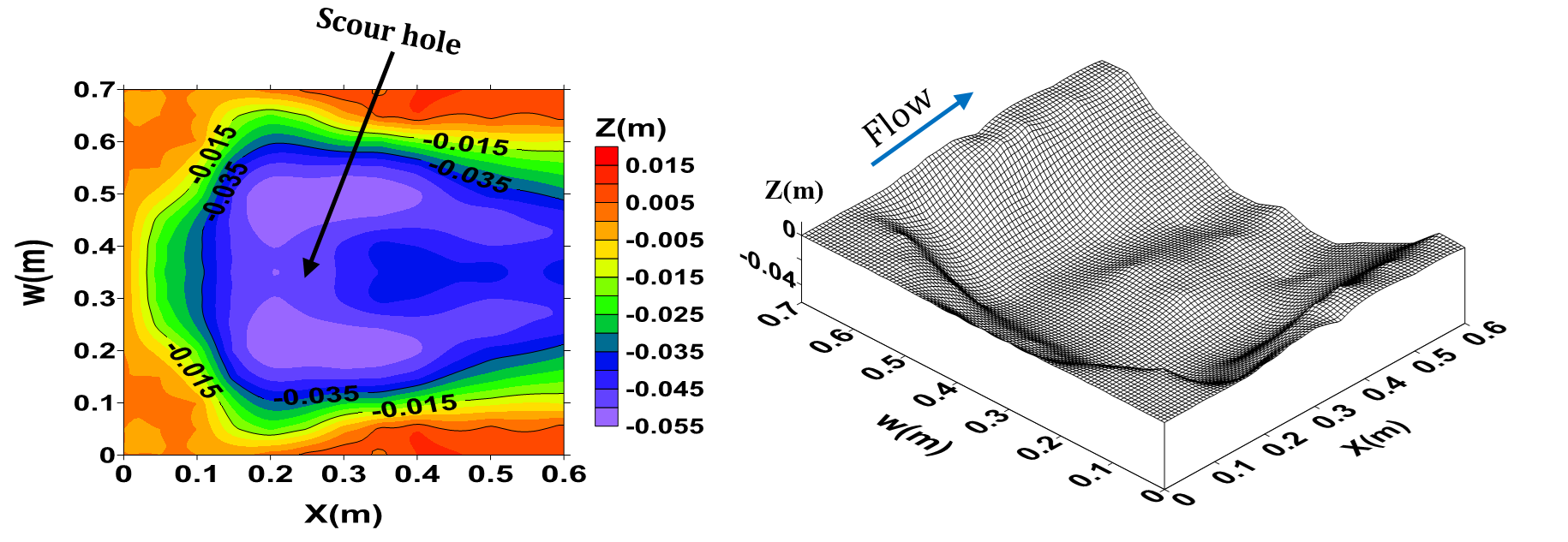
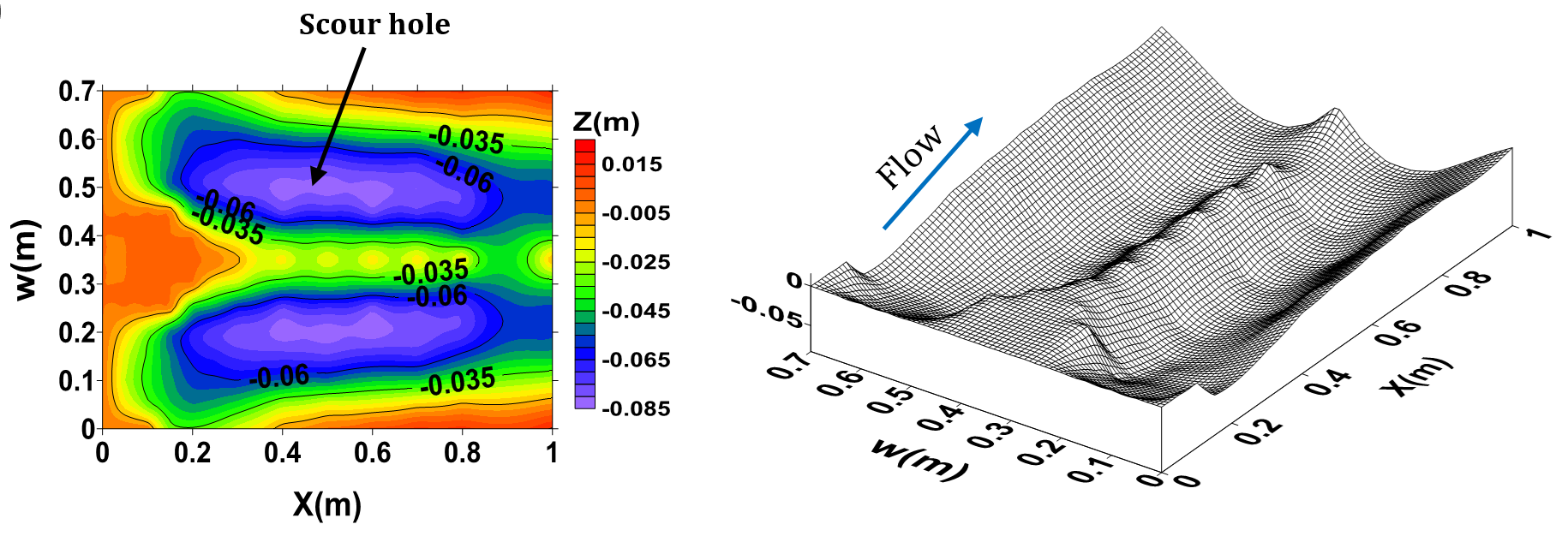
The three dimensional pattern of bed scouring and also the contour lines of scouring at the downstream of the bed sill models are presented in Figure 5. According to the results of the experimental study, it can be concluded that not only the pattern of the bed scouring and maximum scouring hole occurred in very different pattern but also the scouring holes were formed at different locations for different bed sill models.
a) Concave bed sill
b) Convex bed sill
c) Sine bed sill
a) Concave(Test M)
a) Convex(Test N)
a) Sine(Test A)
4. Numerical Model
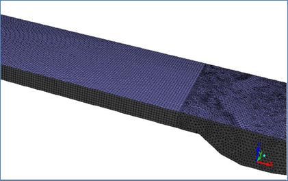
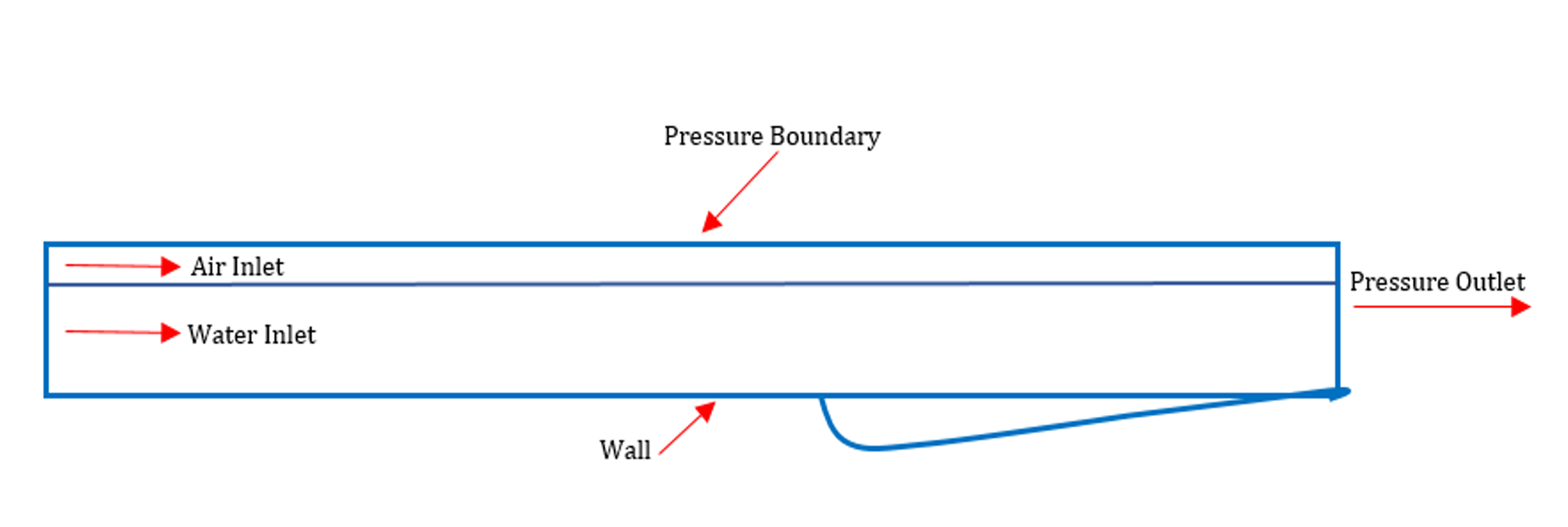
In this study, a software package was used to simulate the flow pattern around different types of bed sill (Figure 3). In order to simulate flow structure, the topographical dimensions of scouring pattern were transferred to the software. Then the model was imported into the software. Mathematical model is based on continuity and momentum equations. To determine the free surface of flow, a VOF model was used. In this study, only k-ε turbulence model was used for calculation. To reduce computing time, only a certain section (test section) of the channel was simulated. The test section was selected at a location which is far from inlet to have a fully developed flow at the test section. Also the flume was long enough to have no downstream effect on flow at the test section. Figure 6 illustrates that a structure and unstructured mesh was used in each model with a mesh study used to select the most effective mesh. Boundary conditions include the entrance section, output section, walls and free surface of the boundary. The applied boundary conditions are shown in Figure 7.
5. Error Criterion
Average Relative Error (ARE) formula was used to evaluate the numerical and experimental models. Equation 1 shows the relative error between experimental and numerical results.
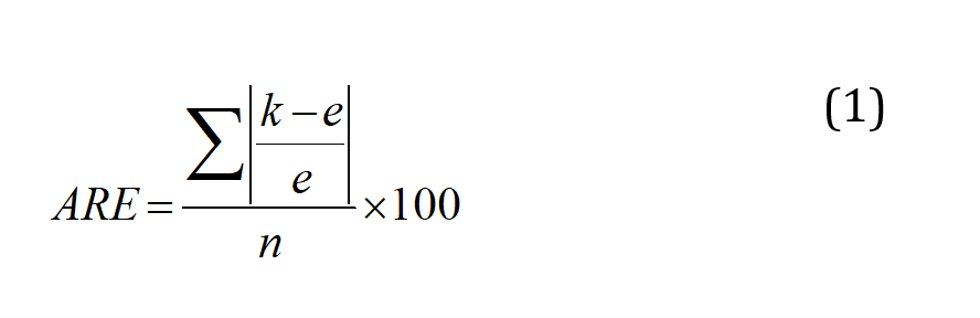
In which k=simulated numerical data, e=experimental data and n=number of total data.
6. Results and Discussion
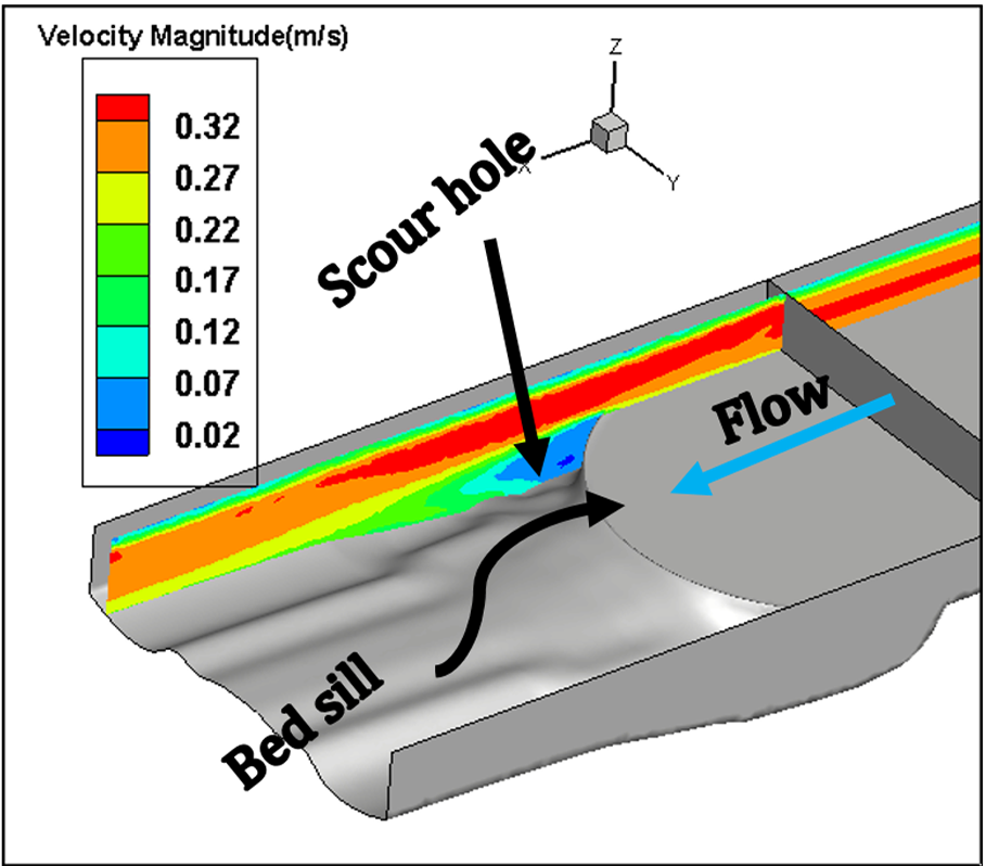
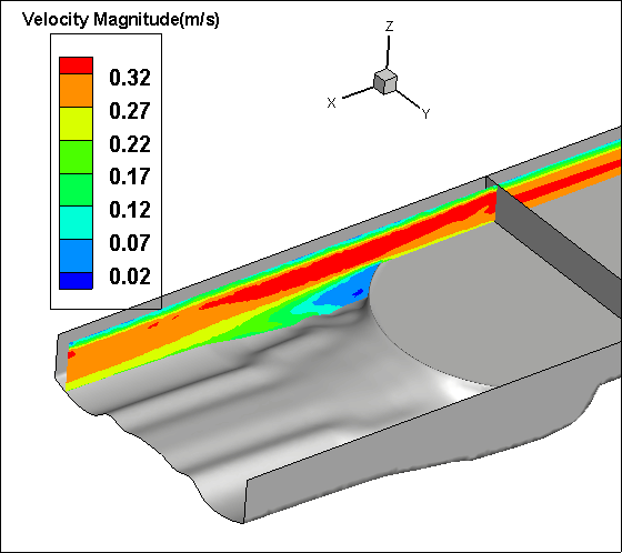
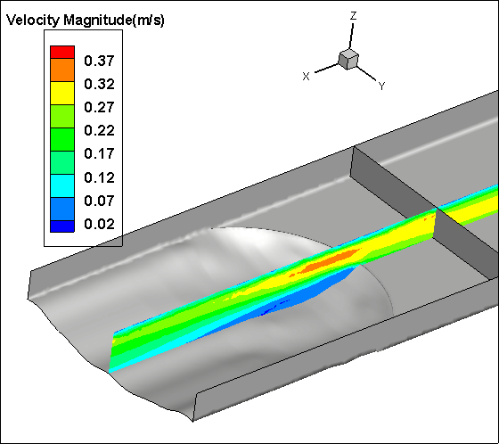
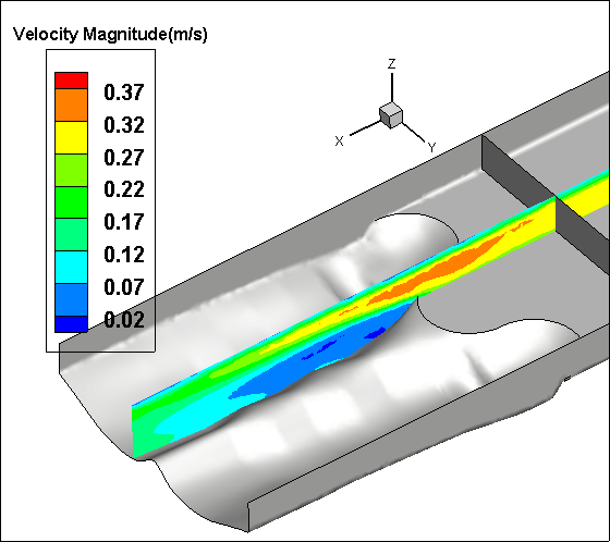
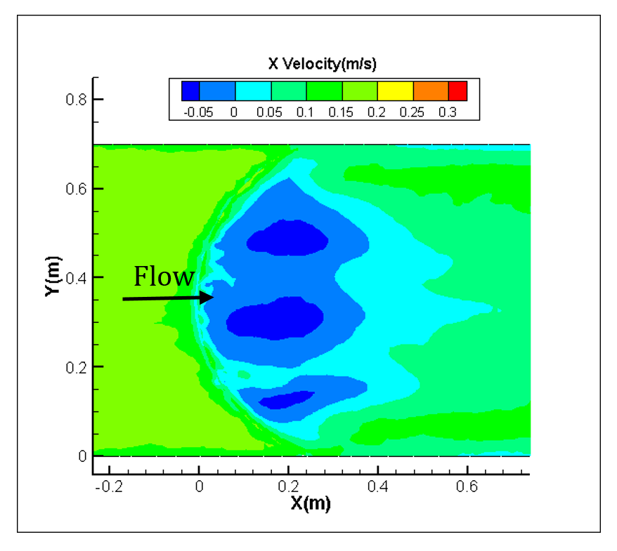
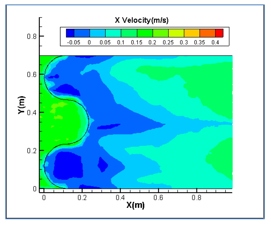
In this study, the numerical analysis is done for only one type of Concave, Convex and Sine bed sills hereafter referred as M, N and A as labelled in the set of experimental tests. The concave bed sill protects some sections of the channel by creating vortices at the bank. These vortices transfer the sediment particles to the middle section of the channel. The flow condition is presented in Table 1. Figure 8 represents the velocity contours in longitudinal and transverse sections of the channel. In Figure 8, it is obvious that by receding from the wall, the negative velocity decreases constantly and this phenomenon transfers the sediment particles towards the centre of the flume. Moreover, the longitudinal section illustrates a growth in separation zone by approaching from middle to the banks of the channel. Therefore, strong vortices are created at the banks of the channel. This process increases the scouring hole in this zone. Also as it is mentioned earlier in this paper, the convex bed sill has an ability to stabilize the banks of the channel by transferring the sediment from the centreline with transition of vortices in the middle towards the banks of the channel. The longitudinal section shows that by approaching towards the centre of the channel, the separation zone increases. The sine bed sill is a combination of convex and concave bed sills, therefore enables to protect banks and the centreline. It moves vortices away from the wall but not to the centreline. The numerical analysis indicates that the maximum scouring depth location is between the wall and centre of the channel. Figure 8 illustrates the longitudinal section of velocity contours. It is proposed that the Sine bed sill has a minor separation zone at the banks of the channel which increases by approaching towards the centre of the channel.
 (a) 0.02 m from wall
|
 (a) 0.35 m from wall
 |
| a) Concave | 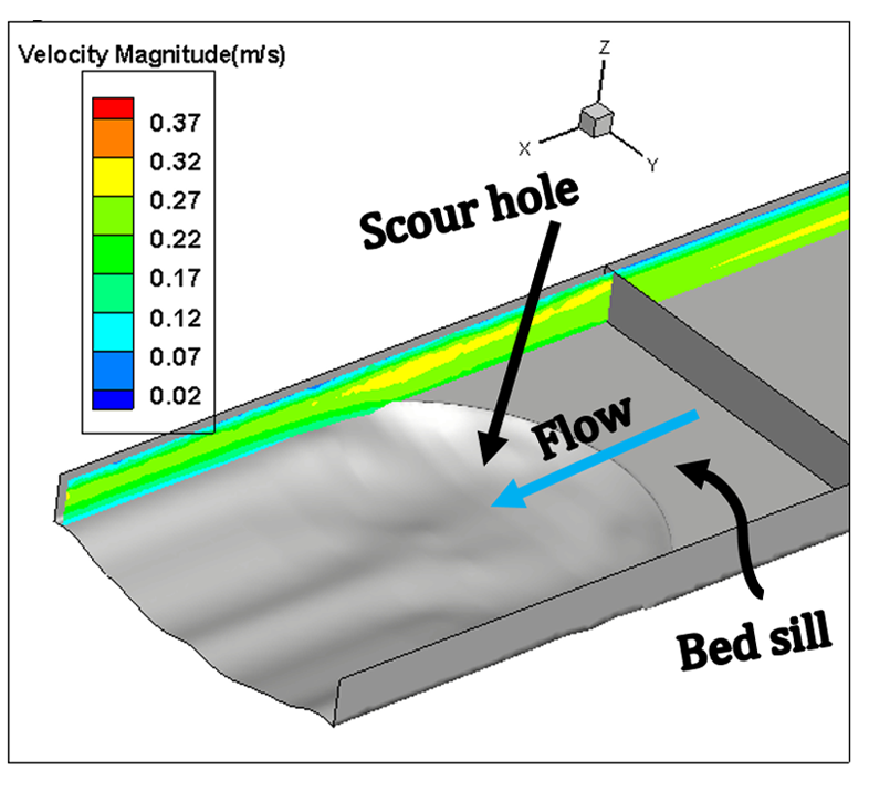 (b) 0.02 m from wall
 |
 (b) 0.35 m from wall
|
| b) Convex | 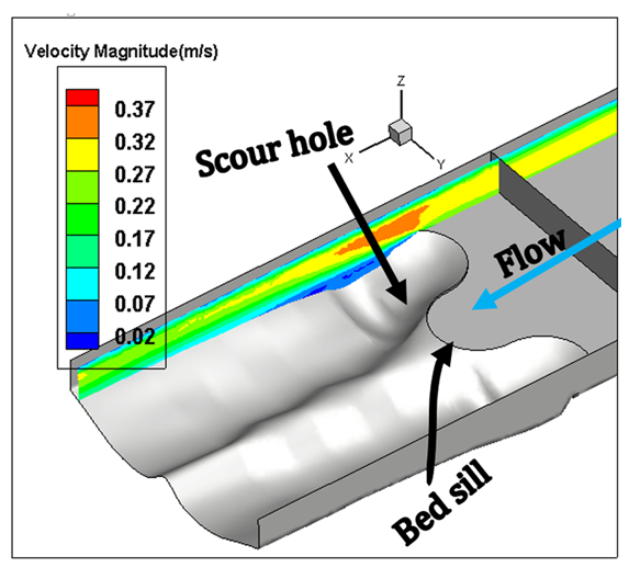 (c) 0.03 m from wall
 |
 (c) 0.27 m from wall
 |
| c) Sine | |
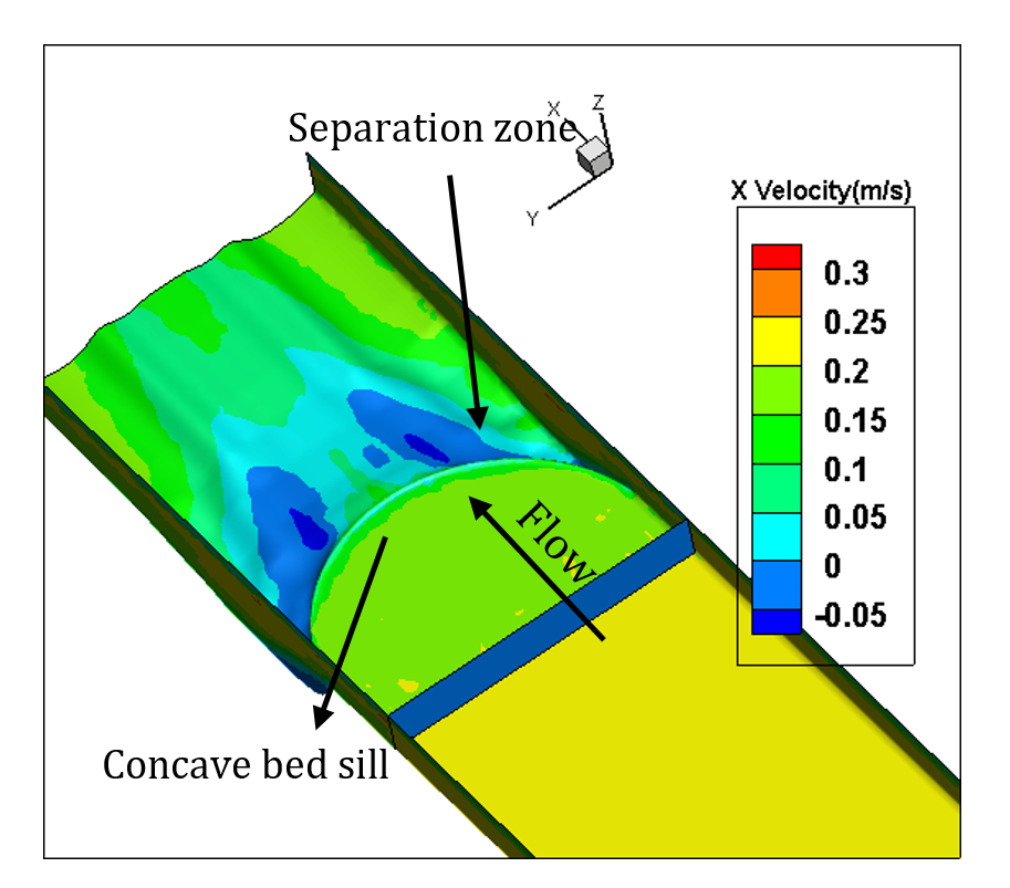
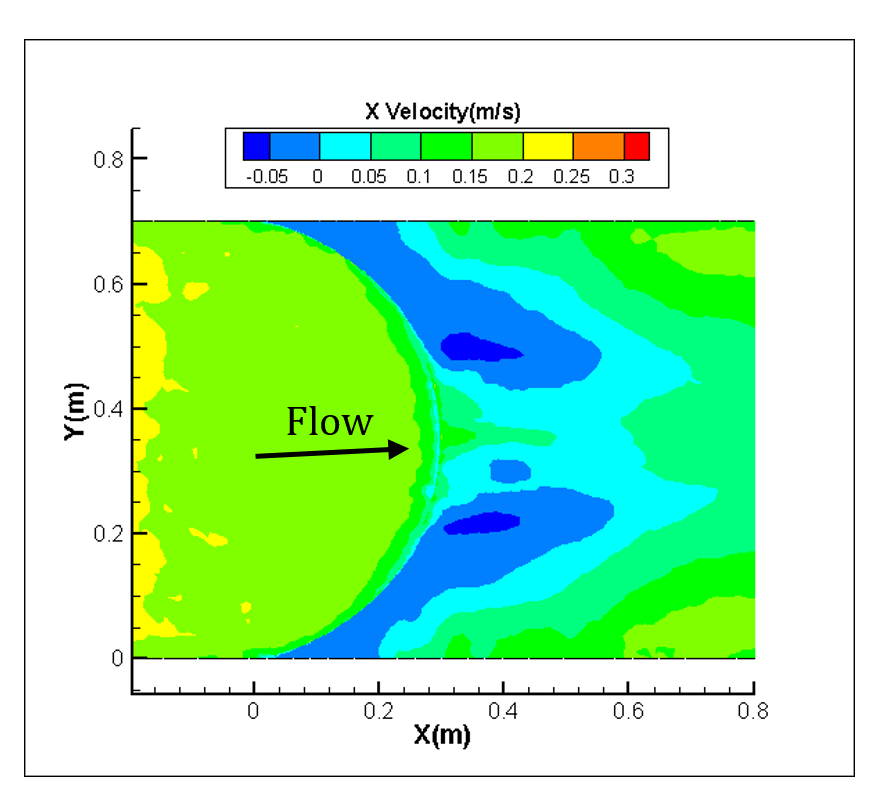
Figure 9 illustrates the X-velocity contours for the concave and convex cases. Maximum velocity occurs at the bank for concave bed sill, however maximum velocity occurs at the centreline of the convex bed sill. As a result, the concave bed sill stabilizes the centreline while the convex bed sill stabilizes the banks. However, the sine shape bed sill is recommended to use when it is needed to stabilize the banks and centreline simultaneously because the locations of vortices are mainly at both centre and at sides of the channel.
|
|
| Concave (Test M) | 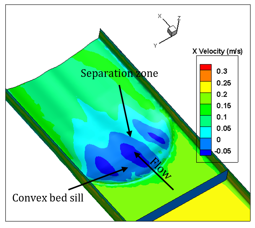
|
|
| Convex (Test N) | 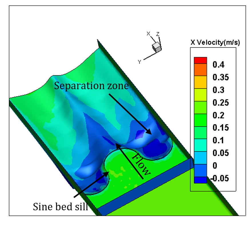
|
|
| Sine(Test A) | |
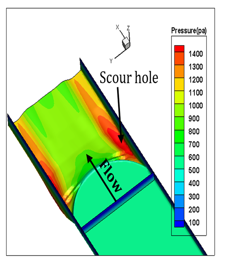
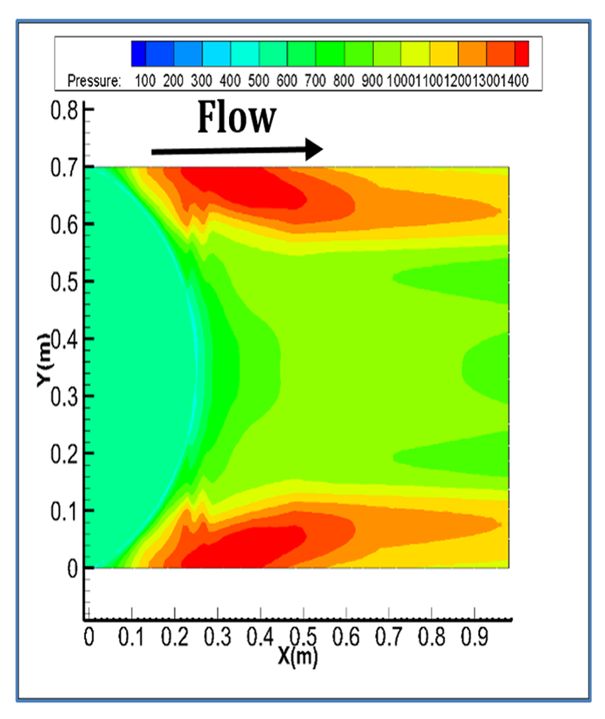
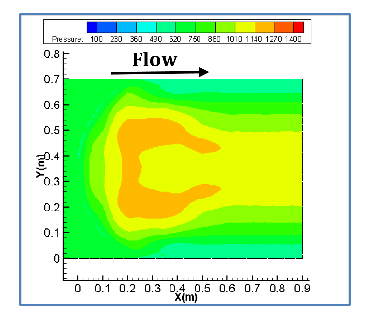
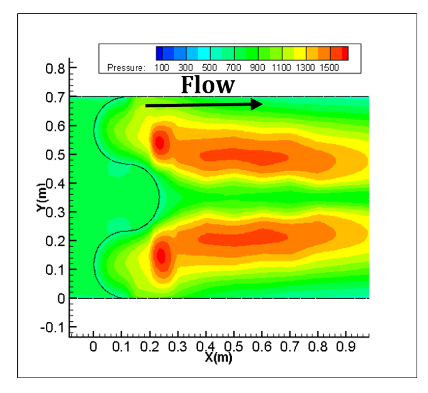
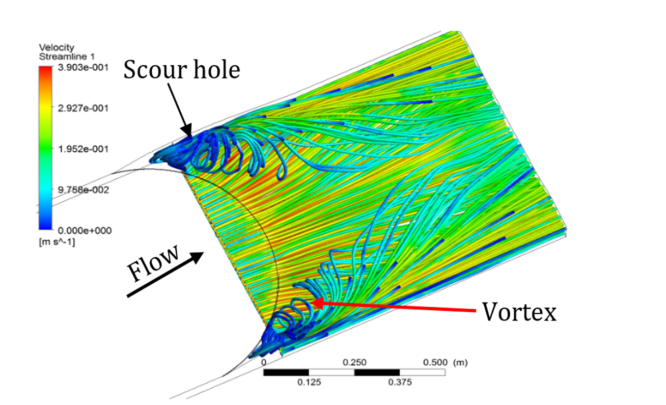
Figure 10 shows pressure gradient for the three bed sill models. As shown in the figure, maximum pressure occurs at the banks, centreline and the area between these two zones related to concave, convex and sine bed sills, respectively. This indicates that the zones with maximum scouring had the maximum pressures. The Sine bed sill is the most effective bed sill for stabilizing banks and centre line. Figure 11 shows the extension of vortices of different bed sills looking upward from the bottom of the channel.
|
|
| a) Concave (M) | 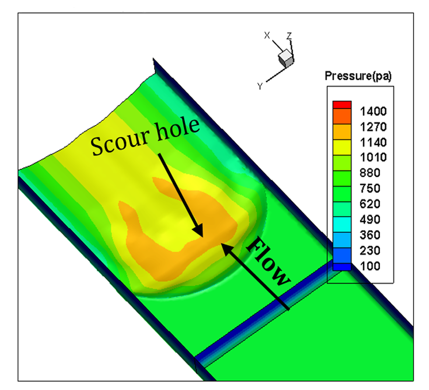
|
|
| b) Convex (N) | 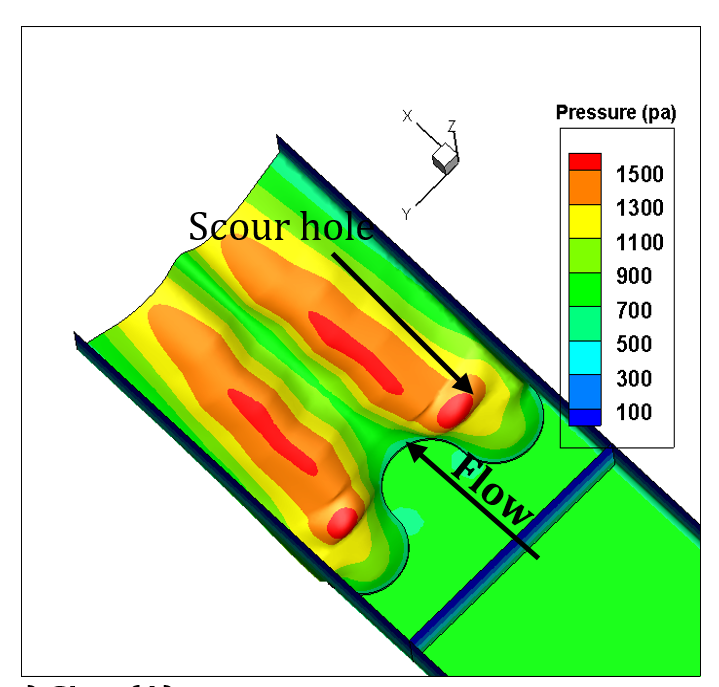
|
|
| c) Sine (A) | |
|
|
| Concave (M) | 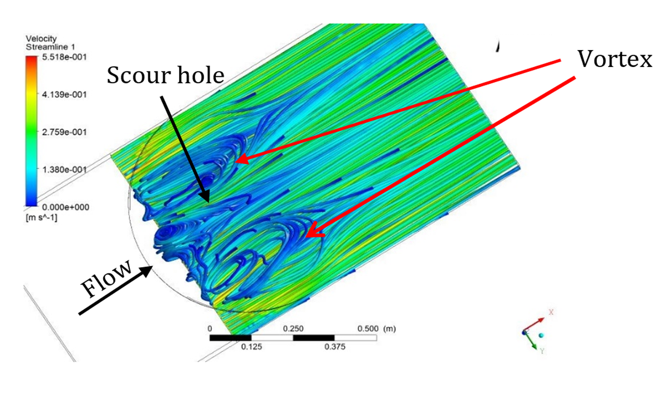
|
| Convex (N) | 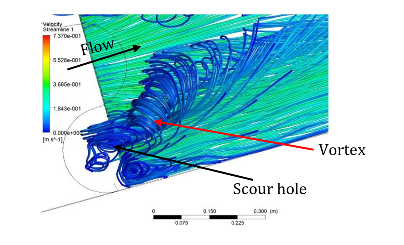
|
| Sine (A) | |
7. Model Validation
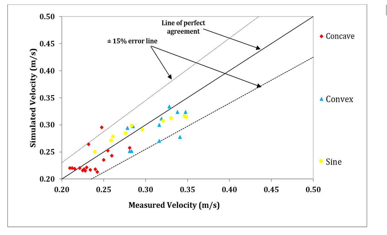
Three simulation models were used in this study. Table 2 shows the percentage of errors between experimental data and the numerical results from the simulation models. Figure 12 shows the results of velocity validation for all types of bed sills. The result shows that for Sine model, the model prediction is very close to line 1:1.
|
Table 1. Flow condition in the experimental tests, maximum scouring, cells and errors.
| Model | Error (%) |
| Concave | 8.6 |
| Convex | 10 |
| Sine | 5.3 |
8. Conclusion
The concave bed sill creates a major separation zone, scouring and vortices at the banks of the channel. The movement of sediment particles to the centreline is due to the transportation of bank vortices to this zone. As a result the centre of channel is stabilized. In contrast, the convex bed sill makes the separation zone, scouring and vortices at the middle section of the channel. Stabilization of the sidesbanks occurs as a result of transportation of sediments ofat the banks with movement of vortices towards the walls. According to the results, in concave bed sill by moving away from the walls, the negative velocity decreases constantly and it transfers the sediment particles towards the centreline of the flume. Also the maximum amount of scouring was found near the banks of concave bed sill (Y/W=0) and location of maximum scouring depth in sine bed sill was at 0.15m (Y/W=0.215) distance from the banks. Furthermore, in the convex bed sills maximum depth of scouring was at the centreline (Y/W=0.5) of the channel. Therefore, selection the type of bed sill depends on location of protection work. According to the results, the maximum and minimum scouring depths were produced by concave and convex bed sills, respectively. However, the sine shaped bed sill enables to protect bank and centreline and it is recommended to use when it is important to stabilize simultaneously banks and centreline sections.
Notation
The following symbols are used in this paper:
K = simulation data
e = experimental data
n = number of total data
ZS = Maximum scouring depth
W = Width of the channel
d50 = Median particle size
T = The arch distance of the circular bed sill
E and P = The diameter of convex and concave bed sills of sine bed sills, respectively
Y= Transverse direction
M= Cancave bed sill
N= Convex bed sill
A = Sine bed sill
CU = Coefficient of uniformity
Cc = Coefficient of curvature
References
[1] M. Ben Meftah and M. Mossa, “Experimental study of the scour hole downstream of bed sills,” in River Flow, M. Greco, A. Carravetta and R. Della Morte Eds. 2004, pp. 585-592.
[2] H. N. C. Breusers, “Conformity and time scale in two dimensional local scour,” in Proc. Symposium on model and prototype conformity, Poona: Hydraulic Research Laboratory, 1996, pp. 1-8.
[3] C. Chinnarasri and D. Kositgittiwong, “Laboratory study of maximum scour depth downstream of sills,” in Proceedings of the Institution of Civil Engineers-Water Management, vol. 161, no. 5, pp. 267-275.
[4] W. D. Erskine, A. Keshavarzi, “Frequency of bankfull discharge on South and Eastern Creeks, NSW, Australia,” Hydrology and Water Resources Symposium, Water and the Environment, Inst. of Eng., Australia, 1996.
[5] R. Gaudio and A. Marion, “Time evolution of scouring downstream of bed sills,” J. Hyd. Res., vol. 41, no. 3, pp. 271-284, 2003.
[6] D. Guan, B. Melville and H. Friedrich, “Local scour at submerged weirs in sand-bed channels,” Journal of Hydraulic Research, vol. 54, no. 2, pp. 172-184, 2016.
[7] E. Habib, M. Mossa and A. Petrillo, “Scour downstream of hydraulic jump,” Modelling, Testing & Monitoring for Hydro Power Plants Conference, Budapest, Hungary, pp. 561-602, 1994.
[8] N. M. K. N Hassan and R. Narayanan, “Local scour downstream of an apron,” J. of Hyd. Eng., ASCE, vol. 111, no. 11, pp. 1371-1385, 1985.
[9] G. J.C. M. Hoffmans and K. W. Pilarczyk, “Local scour downstream of hydraulic structures,” J. of Hyd. Eng., ASCE, vol. 121, no. 4, pp. 326-340, 1995.
[10] A. Keshavarzi and SH Nabavi, “Dominant discharge in the Kor River, upstream of doroodzan Dam, Fars province, Iran,” Trends in Applied Sciences Research, vol. 2, no. 1, pp. 158-164, 2007.
[11] A. Keshavarzi and L. Khaje Noori, “Environmental protection stability of river bed and banks using convex, concave, and linear bed sills,” Environmental Monitoring and Assessment, vol. 17, no. 1, pp. 621-631, 2010.
[12] A Keshavarzi, H Hamidifar, J Ball, “Bed morphology in vegetated estuarine river with mild-curved meander bend,” Hydrological Sciences Journal, vol. 61, no. 11, 2016.
[13] A. Keshavarzi and M. Sohrabi, “Study on the effect of different bed sills on flow structure and scouring at the bed of channel,” in Proceedings of the 3rd International Conference on Civil, Structural and Transportation Engineering (ICCSTE'18), Niagara Falls, Canada, June 10–12, 2018.
[14] A. Keshavarzi, R. Gazni, and R. Homayoon, “Prediction of scouring around an arch-shaped bed sill using neuro-fuzzy model,” Applied Soft Computing, vol. 12, pp. 486–493, 2012.
[15] A. Keshavarzi, C. K. Shrestha, B. Melville, H. Khabbaz, M. Ranjbar-Zahedani, and J. Ball, “Estimation of maximum scour depths at upstream of front and rear piers for two in-line circular columns,” Environmental Fluid Mechanics, vol. 18, no. 2, pp. 537-50, 2018.
[16] A. Keshavarzi, C. K. Shrestha, M. R. Zahedani, J. Ball, J. and H. Khabbaz, “Experimental study of flow structure around two in-line bridge piers,” ICE - Water Management, 2017.
[17] M. A. Lenzi, A. Marion, F. Comiti, and R. Gaudio, “Local scouring in low and high gradient streams at bed sills,” J. of Hyd. Res., IAHR, vol. 40, no. 6, pp. 731-739, 2002.
[18] N. Niknia, A. Keshavarzi, and Z. Hosseinipour, “Improvement the Trap Efficiency of Vortex Chamber for Exclusion of Suspended Sediment in Diverted Water,” World Environmental and Water Resources Congress, Palm Springs, California, United States, May 22-26, 2011.
[19] M. Ranjbar-Zahedani, A. Keshavarzi, H. Khabbaz, and J. Ball, “Protecting bridge pier against local scour using flow diversion structure,” ICE-Water Management, 2018.
[20] M. Sohrabi, A. Keshavarzi, and M. Javan. “Impact of Bed Sill Shapes on Scour Protection in River Bed and Banks,” accepted for publication in The International Journal of River Basin Management, 2018.
[21] A. Tafarojnoruz, R. Gaudio, S. and Dey, “Flow-altering countermeasures against scour at bridge piers: a review,” Journal of Hydraulic Research,vol. 48, no. 4, pp. 441-52, 2010.
[22] M. Tregnaghi, “Local scouring at bed sills under steady and unsteady conditions,” Ph.D. Thesis, University of Padova: 161, 2008.
[23] U.S. Army Corps of Engineers, “River hydraulics, Engineer Manual” (Report EM 1110-2-1416). Washington, DC: Department of the Army,i> 176 pages, 1993.
[24] P. Volkart, J. Tshopp and E. Bisaz, “The effect of sills on river bed,” Proc. of Int. Symp. on River Mechanics, IAHR, Bangkok, pp. 167-178, 1973.
[25] A. N. Ziaei, J.M. McDonough, H. Emdad, and A. Keshavarzi, “Using vorticity to define conditions at multiple open boundaries for simulating flow in a simplified vortex settling basin,” Int. J. for Numerical Methods in Fluids, vol. 54, no. 1, pp. 1-28, 2007.