International Journal of Civil Infrastructure (IJCI)
ISSN: 2563-8084

Volume 3 - Year 2020- Pages 7-14
DOI: 10.11159/ijci.2020.002
3D numerical analysis of passive pile groups adjacent to deep braced excavation in soft clay
Runhong Zhang1, Anthony Teck Chee Goh2, Wengang Zhang134*
1School of Civil Engineering, Chongqing University,
Chongqing 400045, China
zhangrh@cqu.edu.cn; cheungwg@126.com
2School of Civil and Environmental Engineering,
Nanyang Technological University, 639798, Singapore
CTCGOH@ntu.edu.sg
3Key Laboratory of New Technology for Construction of Cities in Mountain Area,
Chongqing University, Ministry of Education, Chongqing 400045, China
cheungwg@126.com
4National Joint Engineering Research Center of Geohazards Prevention in the Reservoir Areas,
Chongqing University, Chongqing, 400045, China
cheungwg@126.com
Abstract - This paper analyzes responses of pile groups adjacent to deep braced excavation in soft marine clay by 3D finite element method, based on field instrumented case history. Pile groups comprising of 2×1, 4×1, 8×1 and 8×2 piles with center-to-center spacing of 2d and 3d, respectively, were numerically investigated. The group factor in terms of the maximum pile bending moment is carried out to examine the effects of pile diameter, pile spacing, and pile number on the group effects. The group factor for the center piles and edge piles, as well as the front piles and rear piles in a two-row pile group, are compared. Conclusions arrived at in this study can provide design guidelines for deep braced excavations with adjacent foundation piles considering the pile-soil interaction and pile group effect.
Keywords: Finite element analysis, Braced excavation, Pile group factors, Soft clay, Soil-pile interaction.
© Copyright 2020 Authors - This is an Open Access article published under the Creative Commons Attribution License terms. Unrestricted use, distribution, and reproduction in any medium are permitted, provided the original work is properly cited.
Date Received: 2020-02-20
Date Accepted: 2020-03-02
Date Published: 2020
1. Introduction
Deep braced excavations may lead to surrounding soil movement and introduce passive loading onto the nearby piles, which poses a significant threat to the serviceability of the pile group or even causes failure. Plenty of research have been conducted via the in-situ test, centrifuge model test, and numerical methods to investigate the pile responses induced by adjacent excavations and tunnelling operations [1-11, 27-29].
In practice, piles are closely spaced in a group manner when used for ground reinforcement; the existence or installation of piles nearby can affect the subsequent behaviour of each pile. [12] have recognized that the piles within a group may have a smaller bearing capacity compared with the single, isolated piles due to the pile-soil-pile interaction effects. However, due to the lack of a systematic and distinct quantitative understanding of pile group interaction effects, the solution proposed for a single pile is commonly used in engineering practice, even for pile groups [13]. Therefore, it is essential to get a better understanding of complex pile-soil-pile interaction within the pile group subjected to lateral soil movement induced by adjacent deep excavation.
During construction, there are some circumstances under which the foundation bored piles are installed and left aside with free head and no axial loading[15]. When encountering the simultaneous construction of the adjacent braced excavation, it concerns the usability of the bored piles in the future. Researchers such as [16-18] have studied the group factors of free head pile groups subjected to lateral soil movement. However, most of the studies were based on active soil pressure caused by lateral loadings on the piles, or by applying soil flows around the pile through the model test apparatus. Therefore, it cannot clearly explain the behaviours of passive piles near excavations. The soil around the pile is subjected to a stress release process caused by the nearby excavations, in which the unloading soil strength is much smaller than the loading condition.
This paper analyses a series of pile groups adjacent to deep braced excavation in soft marine clay by 3D finite element method, based on field instrumented case history. Pile groups comprising of 2×1, 4×1 and 8×2 piles with center-to-center spacing of 2d and 3d, respectively, were numerically investigated. The group factor in terms of the maximum pile bending moment is carried out to analyze the effects of pile diameter, pile spacing, and pile number on the group effects. The group factor for the center piles and edge piles, as well as the front piles and rear piles in a two-row pile group, are compared. Conclusions arrived at in this study can provide design guidelines for deep braced excavations with adjacent foundation piles considering the pile-soil interaction and pile group effect.
2. Finite element methods
2. 1. Model validation
This study analyses a series of 3D FE models of the pile groups subjected to braced excavation in soft marine clay using the numerical package Plaxis3D[14], and investigates the influences of the pile diameter, pile spacing, and pile number on piles’ bending moments and pile group factors. Before that, a well-instrumented case history validated the 3D finite element analysis.
The prototype of the FE simulation is an actual full-scale instrumented deep cut-and-cover tunnel [15]. The excavation was supported by diaphragm walls of 31.0 m length and 0.8 m thickness, as well as six levels of struts. A row of bored piles of 1.0 m diameter and 46.0 m length were located 3.0 m behind the wall. The final excavation level was 16.0 m below the ground surface, and the maximum lateral pile deflection was 28.0 mm.
The hardening soil (HS) constitutive model is adopted for the soft caly. Table 1 shows the properties of the soil layers. Sand fill and loose sand are considered as drained using c’ and φ’, while clays are considered as undrained using cu. The Plaxis3D default values are used to define the coefficient of earth pressure at-rest K0nc, the Poisson’s ratio υur and the reference pressure pref with K0nc = 1 – sinϕ, υur = 0.2 and pref =100 kPa, respectively, and the power values for stress level dependency of the stiffness m are 0.8 and 1.0, respectively for sand and clay. The soil is modelled using 10-node tetrahedral elements, and 12-node interface elements are used to simulate the soil-structure interaction behaviour. According to [19-20], for simulating the piles subjected to lateral loading, the embedded beam has a trend of overestimation in modelling the pile with the “smoother” shaft surface. However, in this study, the interface factor Rinter is considered as 0.67 for the soft marine clay layer. Therefore, in this study, piles are simulated using 10-node tetrahedral volume elements with the material of non-porous linear-elastic material, instead of commonly used 6-noded plate elements as the embedded beam. The typical 3D numerical mesh comprising of 35,817 nodes and 53,954 elements is shown in Figure 1. The mesh density of soil elements around the piles is enhanced.
Table 1: Summary of soil parameters (HS model).
| Parameters | E50ref (kPa) ×103 | Eoedref (kPa) ×103 | Eurref (kPa) ×103 | cu (kPa) | φ (°) | m | γ (kN/m3) |
| Loose sand | 8 | 8 | 24 | - | 30 | 0.8 | 17 |
| Sand fill | 20 | 20 | 80 | - | 30 | 0.8 | 17 |
| Soft marine clay | 10 | 10 | 30 | 25 | - | 1 | 16 |
| Old alluvium I | 107 | 107 | 320 | 150 | - | 1 | 19 |
| Old alluvium II | 270 | 260 | 900 | 500 | - | 1 | 19 |
Figure 1shows the geometry and typical mesh of the FE model. The nodes on the four side boundary surfaces were fixed horizontally, and the nodes on the bottom boundary surfaces were constrained from moving both horizontally and vertically. The right vertical boundary extends sufficiently far from the excavation area to minimize the boundary effects. The mesh density of soil elements around the piles is enhanced to obtain the precise soil pressure that acts on the piles. Table 2 shows the construction sequence of the FE model.
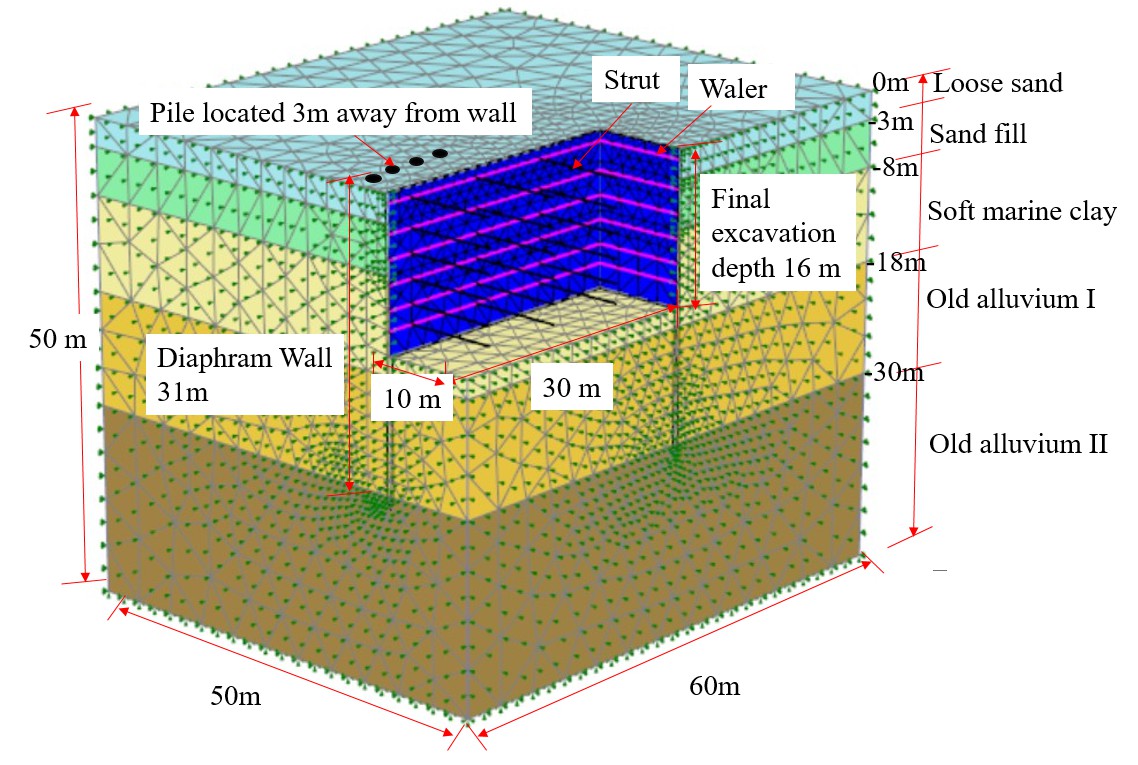
Table 2: Construction sequences.
| Phase | Construction activities |
| Initial Phase | Balance the initial effective stress of the strata with k0 procedure |
| 1 | Install piles (ground surface at y = 0 m) |
| 2 | Reset displacement to zero, install diaphragm walls |
| 3 | Excavate to y = -1m; |
| 4 | Install struts at y = -1 m |
| 5 | Excavate to y = -4 m |
| 6 | Install struts at y = -4 m |
| 7 | Excavate to y = -6.5 m |
| 8 | Install struts at y = -6.5 m |
| 9 | Excavate to y = -9 m |
| 10 | Install struts at y = -9 m |
| 11 | Excavate to y = -11.5 m |
| 12 | Install struts at y = -11.5 m |
| 13 | Excavate to y = -13.5 m |
| 14 | Install struts at y = -13.5m |
| 15 | Excavate to y = -16 m |
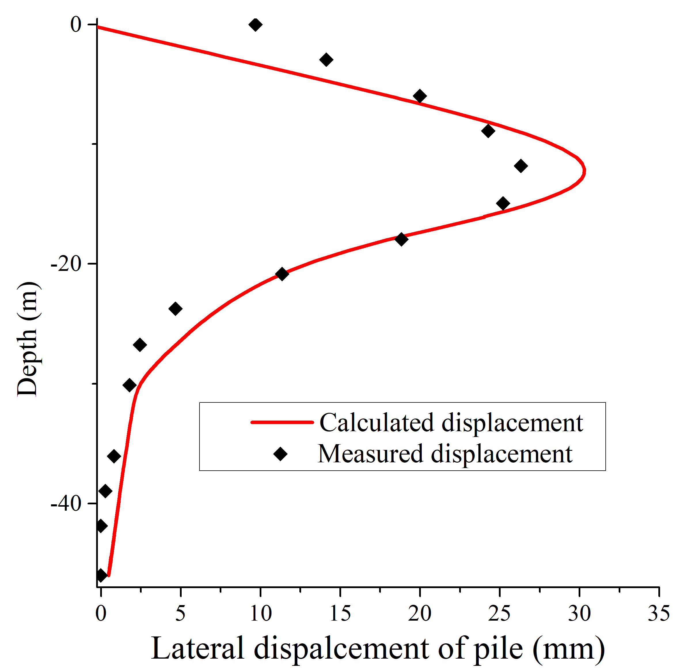
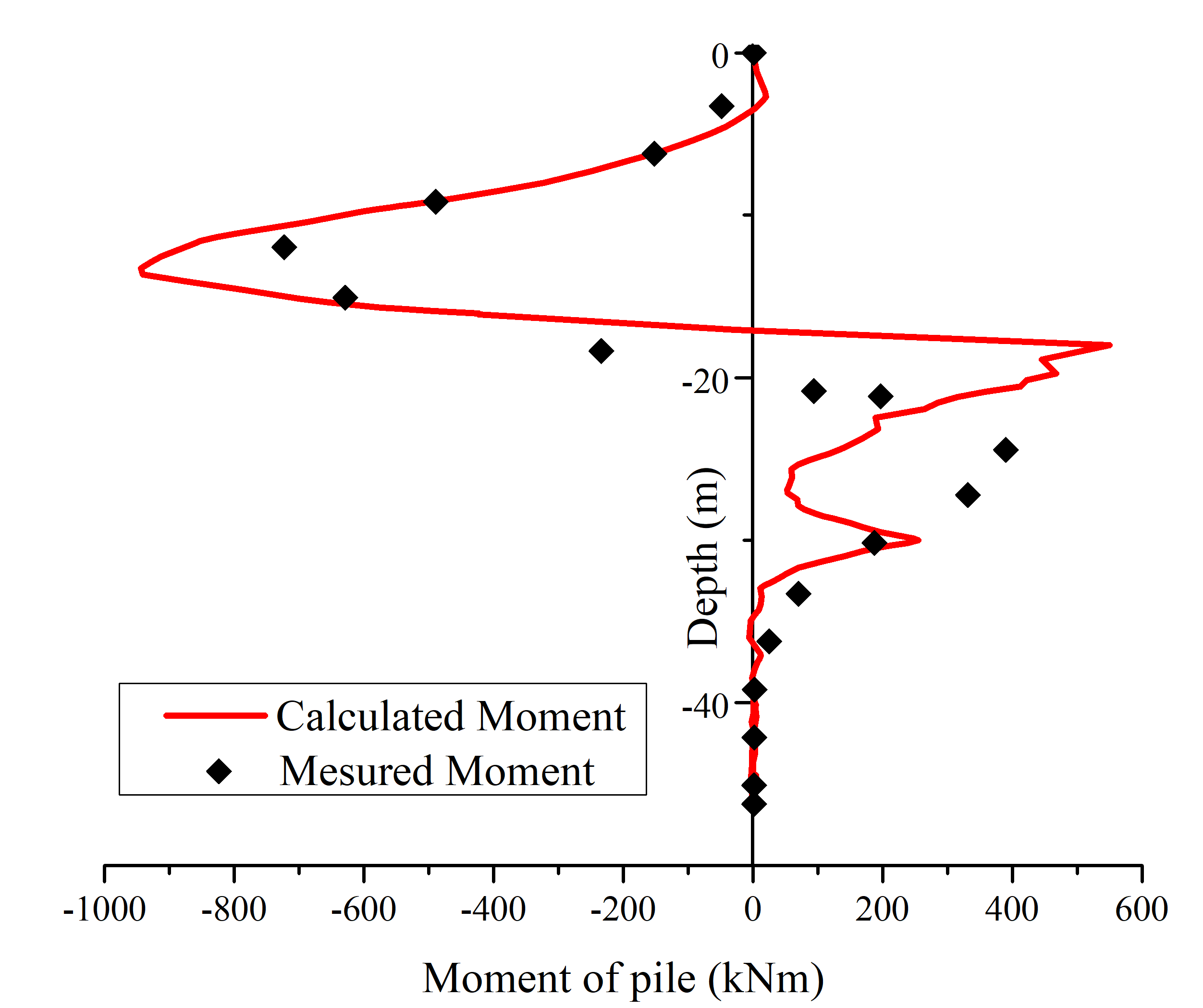
Figure 2 shows the validation of the FEM analysis, which compares the calculated and measured lateral pile deflection and bending moment profiles. The plots indicate that the computed lateral deformation and bending moments are generally in good agreement with the measured results, in both magnitude and shape of the profile. Considering that the bending moments are governed by the curvature of the pile displacement, it is not surprising that the measured and FE moments are not exactly the same. The measured bending moments were obtained by finding an equation that fits the pile displacement (using a curve fitting software), and then differentiating the equation twice to obtain the bending moments (from structural mechanics) [15], so the measured bending moments are also not that accurate. Last but not the least, there is certain spatial variability of the soil properties which influence the measured results. However, this part was not revealed and considered in the current numerical simulation.
2. 2. Parametric sensitivity analysis
Figure 3 shows the plan layout of the pile group and the diaphragm wall. The sv is spacing in the direction of soil movement, and the sh is the spacing in the perpendicular direction of soil movement. The one-row pile group is at the same location as the front row of the two-row pile group. Table 3 lists the ranges of the sv, sh, d, Np(the number of piles in one case).
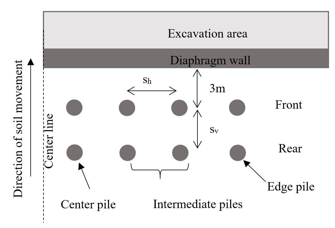
Table 3. The parameters and ranges.
| Parameters | Ranges | Units |
| sh | 2d, 3d | m |
| sv | 2d, 3d | m |
| d | 0.4, 1.0 | m |
| Np* | 1, 4, 8, 16 | - |
*The number of piles in one case.
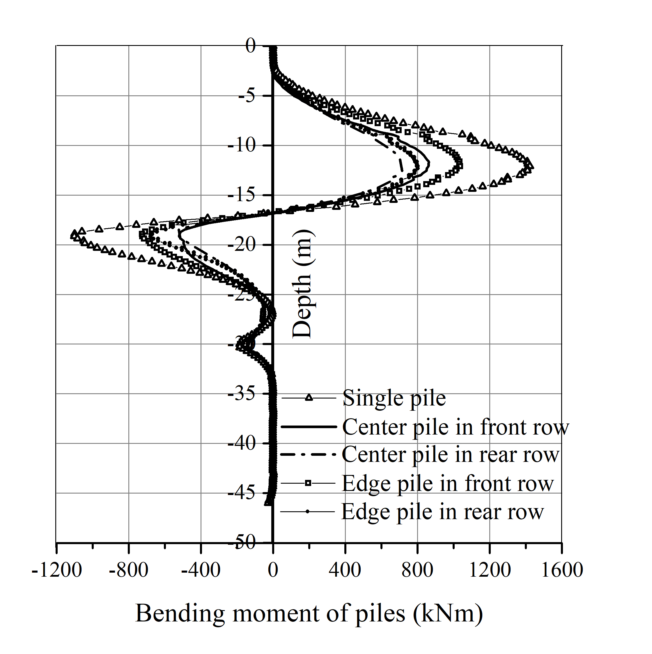
Figure 4 plots the comparison of the bending moments between the pile group (8×2 group with sv=3d, sh=2d) and a single isolated pile. The bending moments of piles in the pile group are significantly reduced, especially for the front row piles. Moreover, the group effect on the center piles is less significant than the edge piles.
3. Assessment of different types of group factor
Group effects on the lateral response of vertical piles subjected to lateral soil movements have been studied numerically by previous researchers. However, the assessment of different types of group factors has not been systematically discussed, and a suitable comparison method is desired to investigate the group effects on the lateral pile response. [21] suggested assessing the group effects in terms of loadings or head deflections for laterally loaded piles. [22] used the pile bending moment for evaluating the group effect on the lateral pile response in analyzing the slope/pile system subjected to lateral soil movements. [23] also studied the braced excavation induced pile group factors using the maximum pile bending moment. The expression is as follows:
in which Mmax,g is the maximum pile bending moment for the pile in a group while Mmax,s is the maximum pile bending moment for a single isolated pile.
In [17], the group factor Fp, which was calculated in terms of the limiting pile-soil contact pressure, was based on plane-strain FE analysis of piles in an infinitely long row. [24-25] used the ultimate soil pressure as the criteria. The group effect was assessed by a group factor Fp,p, based on the measured ultimate soil pressure pu:
where puc=ultimate soil pressure of a pile from a coupled pile test, and pus=ultimate soil pressure of a pile from a single pile test.
In general, p-y curves are complicated to calculate from either field instrumentation or model tests. Pile pressure is generally determined by double differentiation of a curve-fit to the pile bending moment distribution, which is measured by strain gauging several locations downwards the pile.This procedure is complicated for passive lateral loading because of the varied load reversals downwards the pile [3]. Moreover, the group factors calculated by puc were consistent with those calculated by the Mmax, according to [24]. For simplicity, this study adopts the group factor Fp,m in terms of the maximum bending moment.
4. Effect of pile spacing on the group factors
Figure 5 shows the influence of the pile spacing on the Fp,m for 4×1 and 8×1 pile group. The pile spacing produces a more significant influence on the center piles than the edge piles in the cases of 4×1 and 8×1 plie group. Moreover, the pile number in a row also has a significant influence on the pile group factors.
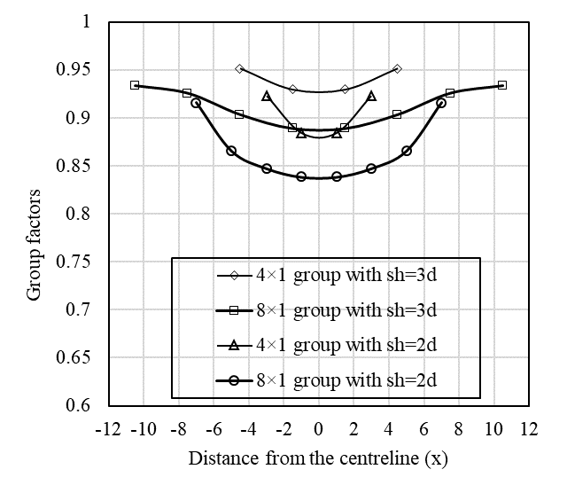
Figure 6 plots the Fp,m for piles in an 8×1 pile group and 8×2 pile group with sv = 2d. As shown in Figure 6(a), the edge effect is more significant for the pile groups with sh =2d than sh =3d. Figure 6(b) and 6(c) indicates that the reduction of pile spacing has more significant influence on the rear piles, since when reducing the sh from 3d to 2d, Fp,m of the center pile in the rear row decreases by 12%, while 9% for center pile in the front row; and the same trend for the edge piles.
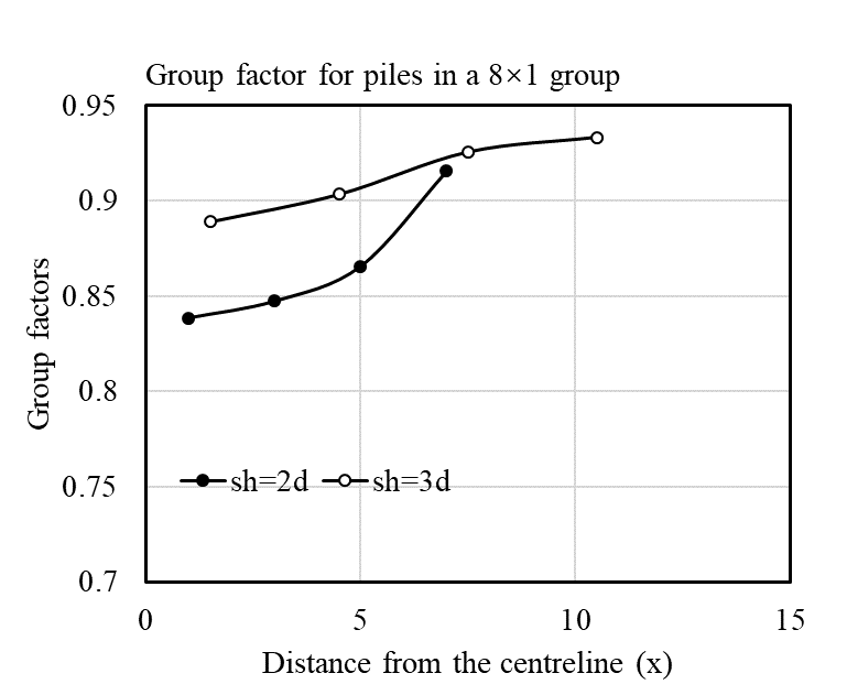
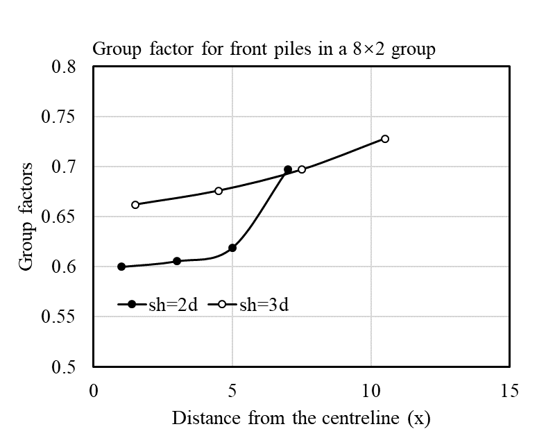
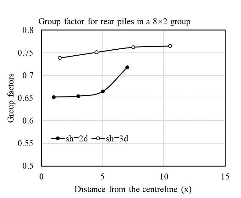
Figure 6. Influence of sh on Fp,m for piles in (a) 8×1 group and (b)front row (c) rear row of 8×2 group.
5. Effect of pile diameter
The effect of the pile diameter on the group factor is investigated by analyzing the pile groups with pile diameters of 1.0 m and 0.4m. The pile spacings of sv=2m and sh=3m, sv=2m and sh=2m are considered. When comparing Figure 7(a) and 7(b), for the center piles, the effect of the pile diameter is more significant with a greater sh. For example, in Figure 7(a) with sh=3m, the Fp,m decreases by 0.11 (from 0.85 to 0.74) for center pile in the rear row when the pile diameter changes from 0.4m to 1.0m; while in Figure 7(b), for the same pile, the Fp,m decreases by 0.15 (from 0.80 to 0.65) when sh=2m. A similar trend can be observed for center piles in the front row. However, the trend is not decisive for the edge piles.
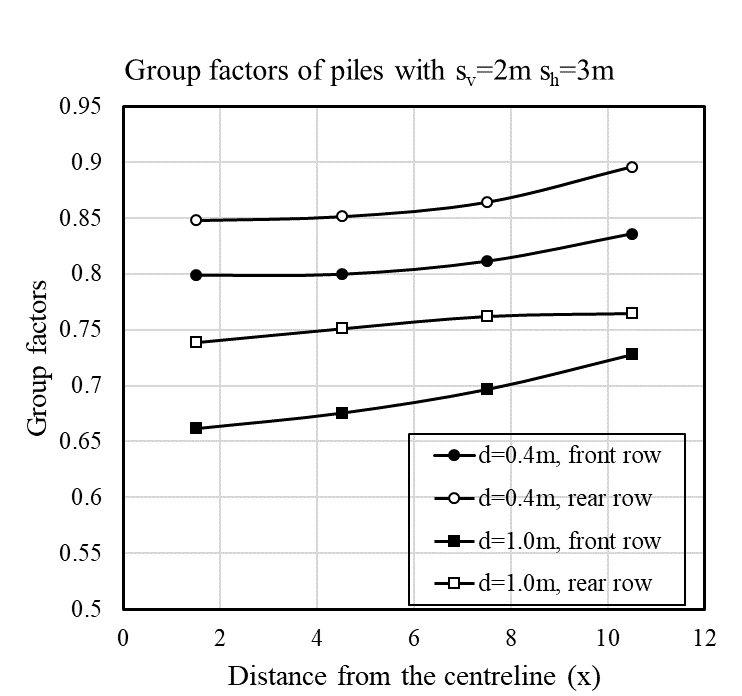
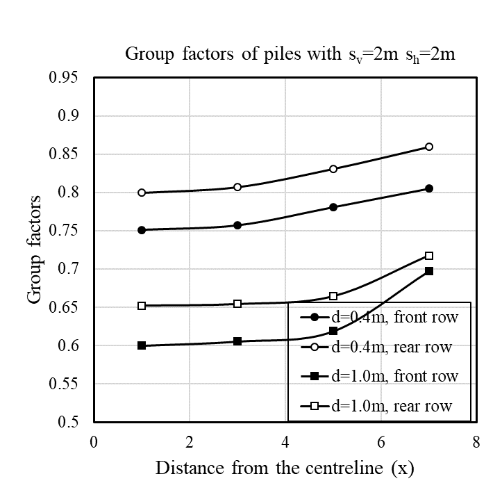
Figure 7. Influence of pile diameter on the Fp,m for piles spacing (a) sv=2m sh=3m and (b) sv=2m sh=2m.
6. Shielding effect of piles
[26] investigated the shielding effect of free-head pile groups adjacent to excavations by numerical simulations and centrifuge tests and concluded that the shielding effect is only significant when the excavation is deep. In this section, the shielding effect of d =1.0m piles with sv = 2d, sh = 2d and 3d is analyzed. As shown in Figure 8, the shielding effect of the front piles on the rear piles is very significant. For example, the group factor of the center pile in the rear row with sh = 2d decreases to 0.65. Simultaneously, the group factor of the center pile in the front row with sh = 2d decreases from 0.84 to 0.60, comparing to the one-row pile. Furthermore, the tendency is similar for edge piles. The results are consistent with the conclusion of [30] that the shielding effect of the front piles along beside the retaining wall reduces the adverse effects of soil movement on rear piles. Moreover, the results are also similar to [31] that the induced bending moments on the peripheral piles in a group have higher bending moments when compared to internal piles that benefit from a stronger pile-soil interaction.
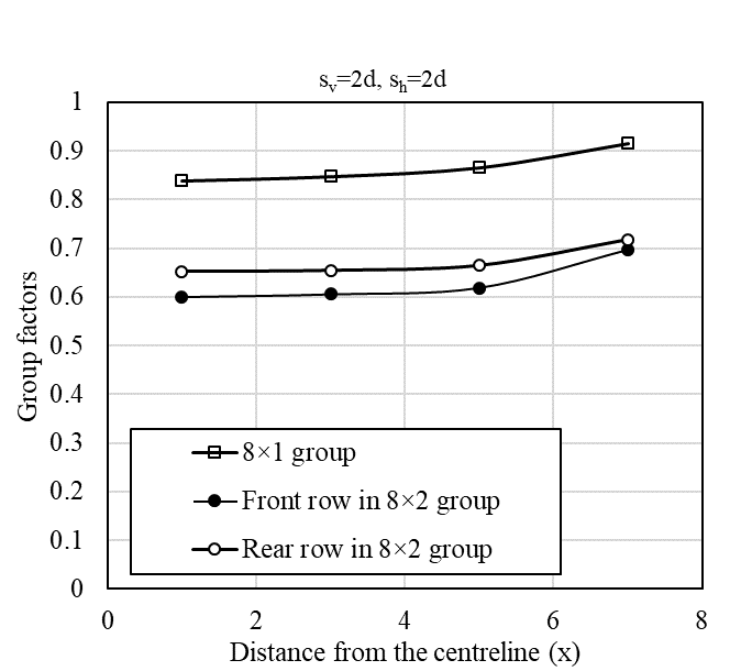
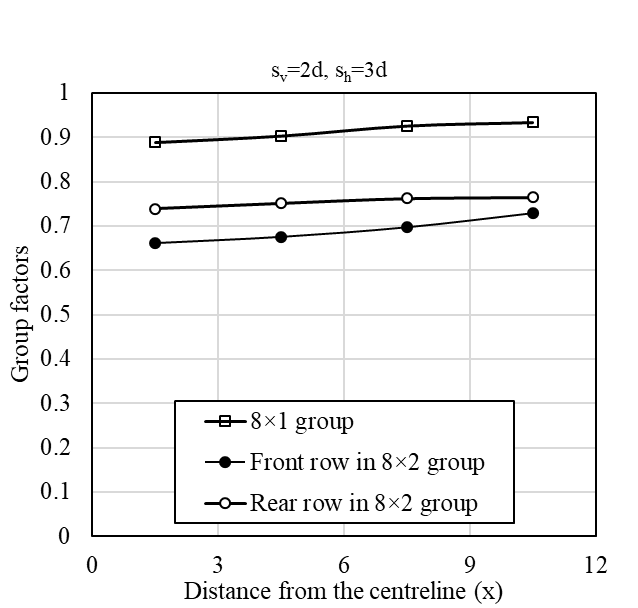
Figure 8. Shielding effect of d =1.0m piles with sv = 2d, sh = 2d and 3d.
7. Conclusions
This paper analyses a series of responses of pile groups adjacent to deep braced excavation in soft marine clay by 3D finite element method, based on field instrumented case history. This study numerically investigated The effects of pile diameter, pile spacing, and pile number on the group factors. The group factor for the center piles and edge piles, as well as the front piles and rear piles in a two-row pile group, are compared.
The pile diameter, pile spacing, and pile number have significant influences on pile groups subjected to braced excavation in soft marine clay. The group effect on the maximum bending moment for center piles is less significant than the edge piles, and the edge piles contribute more to a greater group factor than the central piles, which indicating a marginal effect of the pile groups.
For edge piles in one single row, a greater sh value results in a higher pu value; on the contrary, for the center piles, a larger sh value lead to a lower pu value. The reduction of pile spacing has a more significant influence on the rear piles than the front piles. The effect of the pile diameter is more significant with a larger sh for the center piles but not for the edge piles. The shielding effect of the front piles on the rear piles is considerable.
Acknowledgments
This work was supported by the National Natural Science Foundation of China (No.51608071), Chongqing Engineering Research Center of Disaster Prevention & Control for Banks and Structures in Three Gorges Reservoir Area (Nos. SXAPGC18ZD01 and SXAPGC18YB01) and Chongqing Construction Science and Technology Plan Project (2019-0045). The financial support is gratefully acknowledged.
References
[1] A. T. C. Goh, C. I. The, and K. S. Wong, “Analysis of piles subjected to embankment induced lateral soil movements,” Journal of Geotechnical and Geoenvironmental Engineering, vol. 123, pp. 792-801, 1997. View Article
[2] H. G. Poulos and L. T. Chen, “Pile response due to excavation-induced lateral soil movement,” Journal of Geotechnical and Geoenvironmental Engineering, vol. 123, no. 2, pp. 94-99, 1997. View Article
[3] M. F. Bransby and S. Springman, “Selection of load–transfer functions for passive lateral loading of pile groups,” Computers and Geotechnics, vol. 24, no. 3, pp. 155-184, 1999. View Article
[4] F. Q. Chen, J. W. Wang, and Y. C. Liu, “Numerical analysis of pile response due to braced excavation-induced soil lateral movement,” Rock and Soil Mechanics, vol. 29, no. 7, pp. 1971-1976, 2008.
[5] J. L. Pan, A. T. C. Goh, K. S. Wong, and C. I. Teh, “Model tests on single piles in soft clay,” Canadian Geotechnical Journal, vol. 37, no. 4, pp. 890-897, 2000. View Article
[6] D. S. Liyanapathirana and R. Nishanthan, “Influence of deep excavation induced ground movements on adjacent piles,” Tunnelling and Underground Space Technology, vol. 52, pp. 168-181, 2016.View Article
[7] M. Shakeel and C. W. W. Ng, “Settlement and load transfer mechanism of a pile group adjacent to a deep excavation in soft clay,” Computers and Geotechnics, vol. 96, pp. 55-72, 2018. View Article
[8] J. W. Shi, J. Q. Wei, C. W. W. Ng, and H. Lu, “Stress transfer mechanisms and settlement of a floating pile due to adjacent multi-propped deep excavation in dry sand,” Computers and Geotechnics, vol. 116, pp. 13, 2019. View Article
[9] R. K. Madhumathi, and K. Ilamparuthi, “Laboratory Study on Response of Single Pile Adjacent to Supported Cut,” Geotechnical and Geological Engineering, vol. 36, pp. 3111-33, 2018.View Article
[10] R. H. Zhang, W. G. Zhang, and A. T. C. Goh, “Numerical investigation of pile responses caused by adjacent braced excavation in soft clays,” International Journal of Geotechnical Engineering, pp. 1-15, 2018.View Article
[11] Z. G. Zhang, M. S. Huang, C. P. Zhang, K. M. Jiang and M. H. Lu, “Time-domain analyses for pile deflection induced by adjacent excavation considering influences of viscoelastic mechanism,” Tunnelling and Underground Space Technology, vol. 85, pp. 392-405, 2019.View Article
[12] Y. Kim and S. Jeong, “Analysis of soil resistance on laterally loaded piles based on 3D soil–pile interaction,” Computers and Geotechnics, vol. 38, no. 2, pp. 248-257, 2011. View Article
[13] F. Cai and K. Ugai, “Response of flexible piles under laterally linear movement of the sliding layer in landslides,” Canadian Geotechnical Journal, vol. 40, pp. 46-53, 2003. View Article
[14] L. B. J. Brinkgreve, E. Engin, and W. M. Swolfs, Plaxis Manual, PLAXIS bv, Netherlands, 2017.
[15] A. T. C. Goh, K. S. Wong, C. I. Teh, and D. Wen, “Pile response adjacent to braced excavation,” Journal of Geotechnical and Geoenvironmental Engineering, vol. 129, no. 4, pp. 383-386, 2003. View Article
[16] D. A. Brown, L. C. Reese, and M. W. O’Neill, “Behavior of a large scale pile group subjected to cyclic lateral loading,” Journal of Geotechnical Engineering, ASCE, vol. 113, no. 11, pp. 1326-1343, 1987.View Article
[17] L. T. Chen, and H. G. Poulos, “Piles subjected to lateral soil movements,” Journal of Geotechnical and Geoenvironmental Engineering, ASCE, vol. 123, no. 9, pp. 802-811, 1997. View Article
[18] T. Llyas, C. F. Leung, Y. K. Chow and S. S. Budi, “Centrifuge model study of laterally loaded pile groups in clay,” Journal of Geotechnical and Geoenvironmental Engineering, ASCE, vol. 130, no. 3, pp. 274-283, 2014. View Article
[19] T. P. T. Dao, “Validation of PLAXIS Embedded Piles For Lateral Loading,” Master of Science Thesis. Delft University of Technology, 2011.
[20] I. Al-abboodi, and T. T. Sabbagh, “Numerical Modelling of Passively Loaded Pile Groups,” Geotechnical and Geological Engineering, vol. 37, pp. 2747-2761, 2019. View Article
[21] H. G. Poulos, and E. H. Davis, Pile Foundation Analysis and Design. John Wiley and Sons Inc., New York, 1980.
[22] S. Jeong, B. Kim, J. Won, & J. Lee, “Uncoupled analysis of stabilizing piles in weathered slopes,” Computers and Geotechnics, vol. 30, no. 8, pp. 671-682, 2003. View Article
[23] R. Nishanthan, D. S. Liyanapathirana, & C. J. Leo, “Shielding effect in pile groups adjacent to deep unbraced and braced excavations,” International Journal of Geotechnical Engineering, vol. 11, no. 2, pp. 162-174, 2017.
[24] L. F. Miao, A. T. C. Goh, K. S. Wong, & C. I. Teh, “Ultimate Soil Pressures for Pile Groups in Soft Clay Subjected to Lateral Soil Movements,” The Journal of the Deep Foundations Institute, vol. 2, no. 1, pp. 42–51, 2008. View Article
[25] J. L. Pan, A. T. C. Goh, K. S. Wong and C. I. Teh “Ultimate soil pressures for piles subjected to lateral soil movements,” Journal of Geotechnical and Geoenvironmental Engineering, vol. 128, no. 6, pp. 530-535, 2002.View Article
[26] R. Nishanth an, D. S. Liyanapathirana and C. J. Leo, “Shielding effect in pile groups adjacent to deep unbraced and braced excavations,” International Journal of Geotechnical Engineering, vol. 11, no. 2, pp. 162-174, 2017.
[27] M. A. Soomro, D. A. Mangnejo, R. Bhanbhro, N. A. Memon, & M. A. Memon, “3d finite element analysis of pile responses to adjacent excavation in soft clay: effects of different excavation depths systems relative to a floating pile,” Tunnelling and Underground Space Technology, vol. 86, pp. 138-155, 2019. View Article
[28] C. W. W. Ng, J. Q. Wei, H. Poulos, H. L. Liu, “Effects of multipropped excavation on an adjacent floating pile,” Journal of geotechnical and geoenvironmental engineering, 2017.
[29] D. Su, and J. H. Li, “Three-dimensional finite element study of a single pile response to multidirectional lateral loadings incorporating the simplified state-dependent dilatancy model,” Computers and Geotechnics, vol. 50, pp. 129-142, 2013. View Article
[30] D. E. L. Ong, C. E. Leung, and Y. K. Chow, “Behavior of pile groups subject to excavation-induced soil movement in very soft clay,” Journal of Geotechnical and Geoenvironmental Engineering, vol. 135, no. 10, pp. 1462–1474, 2009. View Article
[31] C. F. Leung, J. K. Lim, R. F. Shen, and Y. K. Chow, “Behavior of pile groups subject to excavation-induced soil movement,” Journal of Geotechnical and Geoenvironmental Engineering, vol. 129, no. 1, pp. 58-65, 2003. View Article
[32] R. H. Zhang, A. T. C. Goh, and W. G. Zhang, “System reliability assessment on deep braced excavation adjacent to an existing upper slope in mountainous terrain: A case study,” SN Applied Sciences, 2019. View Article