International Journal of Civil Infrastructure (IJCI)
ISSN: 2563-8084

Volume 4 - Year 2021- Pages 01-08
DOI: 10.11159/ijci.2021.001
Vibration Caused by Rapid Impact Compaction Experimental vs Numerical Results
Omar El Khaled1, Omar Maalej1, Emmanouil Spyropoulos 2
1Trevi Arabian Soil Contractors Ltd, Soil Improvement Division
King Khalid Road, Al Khobar, Eastern Province, Saudi Arabia 31952
okhaled@trevispa.com; omaalej@trevispa.com
2Saudi Aramco, CSD Department
Dhahran, Saudi Arabia
emmanouil.spyropoulos@aramco.com
Abstract - The use of Rapid Impact Compaction (RIC), sometimes referred as Rapid Dynamic Compaction (RDC), has increased significantly in the latest years in Saudi Arabia mainly for large scale and strategic projects due to substantial time and cost saving benefits. Following the concept of Dynamic Compaction, RIC machines have been developed for the compaction of embankments and shallow treatment up to 6m depth, by providing a compaction hammer attached to a strengthened arm of a hydraulic excavator. This paper concludes the minimum required safe distance to prevent any potential damages of RIC on adjacent buildings and buried utilities, based on the results of experimental measurements supported by numerical model results.
Keywords: Rapid impact compaction, Vibration transmission, Safe distance.
© Copyright 2021 Authors - This is an Open Access article published under the Creative Commons Attribution License terms. Unrestricted use, distribution, and reproduction in any medium are permitted, provided the original work is properly cited.
Date Received: 2020-11-20
Date Accepted: 2020-11-22
Date Published: 2021-02-05
1. Introduction
1. 1. Preamble
Rapid impact compaction (RIC) was developed in the late 1990s for the rapid repair of explosion damage to military airfield runways (Allen 1996[1] SAICE 2006[2] Serridge and Synac 2006[3]). As an extension of the concept of weights dropped on the ground, RIC was developed using modified (BSP) hydraulic hammers acting on a steel foot that remains in contact with the ground. It improves the compacted soils by creating “a plug” of denser ground then driving this layer to greater depth, it is a top-down process. The development of RIC technique has closed the gap between superficial compaction techniques such as Roller compaction (RC) and High Energy Impact Compaction (HEIC), and deep improvement techniques such Deep Dynamic Compaction and Vibro Compaction. Though, despite all its advantages, the RIC technique, same as most of the heavy equipment, is generating a considerable ground vibration.
1. 2. Motivation for the study
Rapid impact compaction (RIC) is currently used for many civilian applications, namely in GCC area. The application of RIC technique induces vibration waves that might be harmful for the surrounding vicinity of the working area as like building, structures, sensitive instrumentations and buried pipelines. As the RIC technique is relatively new, comprehensive studies should be initiated to further understand the possible dynamic effect of RIC on its environment.
1. 3. Objective
Numerical model and experimental analysis will be used to gain more knowledge about the vibration resulting from RIC application on Poorly graded Sand and Silty sand material. In the first part of this study, details about the RIC rig and the work sequence are provided. Definition of peak velocity magnitude VR, max is provided in the second part with brief on the allowable peak velocity on buildings and buried utilities as per the British Standard BS 5228:2-2009[4] and Deutsche Norm DIN 4150-3[5] respectively.
Experimental study results where RIC compaction has been used to compact a backfilling layer of 4m thickness, are presented in the third part. The next part of the study is detailing the findings of the numerical simplified models using PLAXIS [6] commercial software.
Both experimental and numerical results will be used to conclude the minimum required safe distance allowing the use of RIC technique with no expected damages on the adjacent structures or buried utilities.
2. RIC Specifications, Applications and Work Sequence
2. 1. RIC Specifications
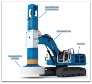
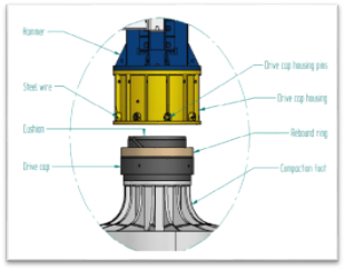
The RIC machine consists mainly of three components: a crawler hydraulic excavator base with a strengthened arm to which a compaction hammer is attached. A weight within the hammer generates compression by the repeated drop onto a compaction foot that remains in contact with the ground.
This compaction energy brings the soil particles into a more densely packed structure. The compaction energy is transmitted safely and efficiently as the compaction foot remains in contact with the ground. No flying debris occurs during the compaction process. The hammering of the foot by the impact weight is the reason of the sub-soil compaction. Indeed, the huge amount of energy developed upon the hammering process and transmitted to the ground through the foot, pushes the backfilling material into a denser structure.
As detailed in the below figure, the compaction foot made from steel with variable diameters ranging between 1.5m and 2.4m. The frame with total weight of 25 tons includes the outer body of the frame, the drive cap housing, the cylinders, the cushion and an impact hammer up to 16 tons capacity.
The maximum drop height could reach up to 1.2m, which generates a maximum impact energy of 188 kNm and a drop rate (blows per minute) ranging between 40 to 100 blows per minute. The hammer is hydraulically lifted to a predetermined height and dropped using hydraulically powered acceleration.
The compaction process can be optimized using an advanced GPS logging system. Using an advanced data logger located inside the cabin, the operator of the RIC rig can easily adjust the compaction energy in terms of the dropping height and the number of blows. He can also record the cumulative settlement, the settlement per blow and the applied energy.
Under normal working conditions, the hammer must be stopped when the recorded penetration is less than 25mm for more than 10 blows, over 6 consecutive intervals of 25mm (For example 60 blows per 150mm).
2. 2. RIC Typical Work Sequence
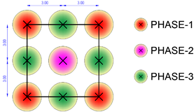
RIC works consists generally of two or three phases, namely Primary grid (Phase-1), Secondary grid (Phase-2) and Tertiary grid (Phase-3). Typical final compaction grid (after all phases) is ranging between 2.5m to 5m. depending on the grading plan, some projects might require that the top surface layer be compacted by the roller compactor after completing the subject RIC works. The optimum grid for a specific project shall be determined based on the field trial, taking into consideration the actual soil conditions and the required technical criteria. The below Figure-2 shows the typical square grid used in the field trial performed for the purpose of this study.
3. Vibration Definition, Limits and Factors for Response Analysis
3. 1. Definition and factors Buildings Response Analysis
The ground borne vibrations can be produced by variable construction activities such as piling, blasting or compaction. It could be also generated by the moving vehicles on road and railways. The dynamic effects of such vibrations might create some substantial problems for the surrounding structures. According to [7-8] The RIC technique generates surfaces waves with frequencies between 2 and 20 Hz. The dominant frequency of ground vibrations changes in the limits of 3-12 Hz (Mitchell 1981 [9] Mayne 1985 [10]).
The surface waves referred as Rayleigh waves, propagating through energy-rich waves in the ground from the vibration source to an adjacent building, buried utilities are the main vibrations to be studied in case of Rapid Impact compaction.
The amplitude of these waves decreases with distance increasing from the compaction point (RIC pounder is considered as the source of vibration) due to the dissipation of energy in the soil itself.
According to the British Standard BS 5228-2:2009 [4], the Peak particle velocity (PPV) is defined as an instantaneous maximum velocity reached by a vibrating element as it oscillates about its rest position. The magnitudes of ground vibrations are usually described in terms of PPV [mm/s].
The velocity is measured in three orthogonal directions namely Radial (x), Transverse (y) and Vertical (z). The peak of velocity magnitude VR,max [mm/s] during a single event is defined as the square root of the sum of the squares of the corresponding velocity components Vx, Vy and Vz [Equation (1)].
As per the British Standard BS 7385:2-1993 [11], several factors could affect the response of a building to ground borne vibration such as: the foundation type, the ground conditions and the interaction between both of them; The type of the structure including its natural frequencies, mode, shape, and damping; The building individual components such as floors, beams or ceilings and the structural system; Size and age of the building; Sensitivity of the building.
3. 2. Allowable Vibration Velocity Limits
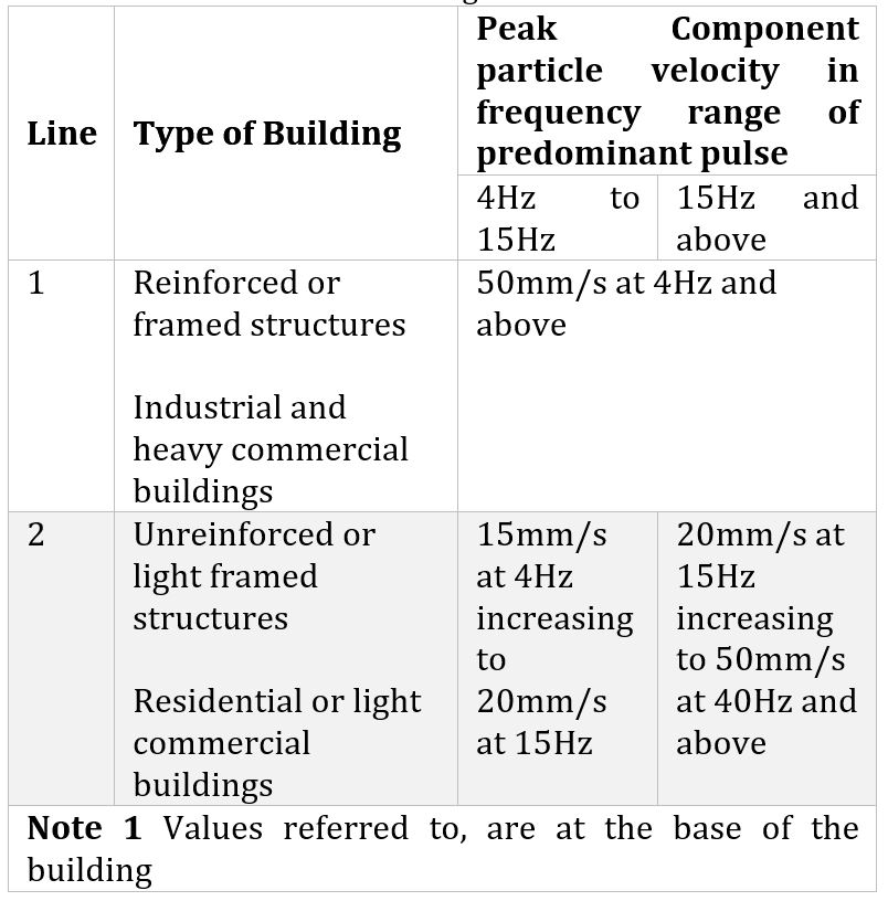
Threshold criteria for the limits of transient vibration above which superficial damage could occur, according to the British Standard BS 5228-2:2009 [4] are given in Table-1:
Table 1: Transient vibration guide values for cosmetic damage.
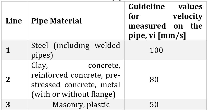
The Deutsche Norm DIN 4150-3 [5] presents the allowable short-term vibration velocity limits on buried pipelines, assuming that pipes has been manufactured and laid according the applicable regulations and standards.
Table 2: Guideline values for short-term vibration velocity on buried pipeline based on Deutsche Norm DIN 4150-3 [5]
4. Experimental Study of Vibration Induced by RIC
4. 1. Trial Details and Device
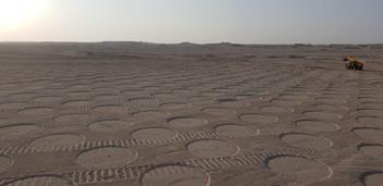
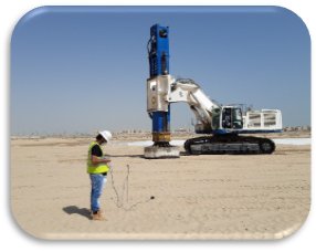
A 16 Tons capacity RIC rig has been used to compact a trial test area with 4m backfilled material of poorly graded Sand and silty sand having a maximum fine content of less than 12%. The trial test area is located in Jubail – Kingdom of Saudi Arabia with 50m by 100m dimensions. The site is an open area where no footings or utilities are located in the vicinity allowing for safe vibration studies.
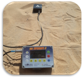
A heavy compaction energy using a 16 tons hammer dropped from a height of 0.7m and 40 blows per print has been applied over three consecutive phases with a final square grid pattern of 3mx3m. The vibration measurements were taken after each phase at variable distance, namely at 3m, 5m, 10m, 20m, 40m, 60m and 90m from the compaction point using a MINI Supergraph II [12] device manufactured by NOMIS SEISMOGRAPHS [12] company.
The device allows for easy and accurate monitoring of ground vibrations and air over-pressure. It monitors the vibrations using Standard Triaxial geophone with range between 0-254 mm/s, a frequency response between 2-400 Hz and with a data accuracy of +/- 3%. The recorded events were then analysed and processed using a software called SuperGraphics 2.
4. 2. Experimental Results
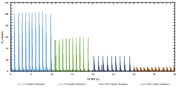
The selected results of vibration monitoring events have been analysed and plotted sequentially as shown in figure 5. As anticipated, the maximum peak velocity magnitude was recorded at 3m from the compaction foot and decreases as much as this distance increases. Indeed, at 3m distance, the peak velocity magnitude reached a maximum of 104 mm/s.
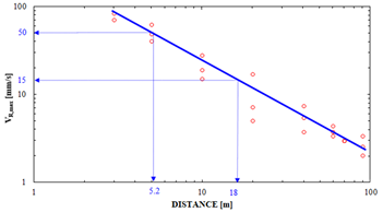
The outcome of RIC generated vibration during the test field has shown that RIC could be safely executed as close as 5.5 to 6m from any existing buried utilities or reinforced structures in order to be within the allowable limit of PPV=50mm/s. The safe distance shall be extended to 18m to respect the allowable limit of PPV=15mm/s for the unreinforced structures or residential buildings.
5. Numerical Study of Vibrations Induced by RIC
A simplified numerical model has been developed using PLAXIS [6] commercial software to study the dynamic impact of the RIC on its environment.
Although, the soil by its nature can be defined as a homogenous half-space with infinite horizontal surface and infinite depth, however the geometry and the loading conditions of the soil compaction induced by RIC allows a significant reduction of the geometric dimension of the mechanical model.
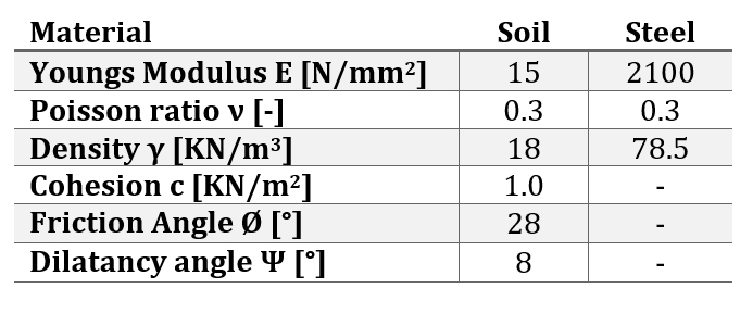
A Mohr-Coulomb plasticity model was used to describe the constitutive behaviour of the soil under impact loading. This model is commonly used for the geotechnical engineering modelling, due to its simplicity and physical clearness. The properties of the material used to develop both models using [6] are summarized in Table 3.
Table 3. Properties of material used in the model
5. 1.1 PLAXIS Single Blow Simulation Results
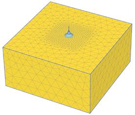
A rectangular prism soil model of 30m width and 15m depth has been defined. The model boundaries has been defined to allow for energy propagation into the semi-infinite half space.
Although the hammer weight of the RIC rig used in the experimental study is 16 tons, however, an exaggerated dropping weight of 25 tons has been used in the numerical model to take account for the hydraulically powered acceleration of the hammer. The sliding surface between the pounder footprint and the soil has been assumed allowing only for the normal stresses transfer. Figure 7 shows the simplified numerical model prepared using PLAXIS [6] to evaluate the vibration results induced by the dynamic load.
(Footprint and soil)
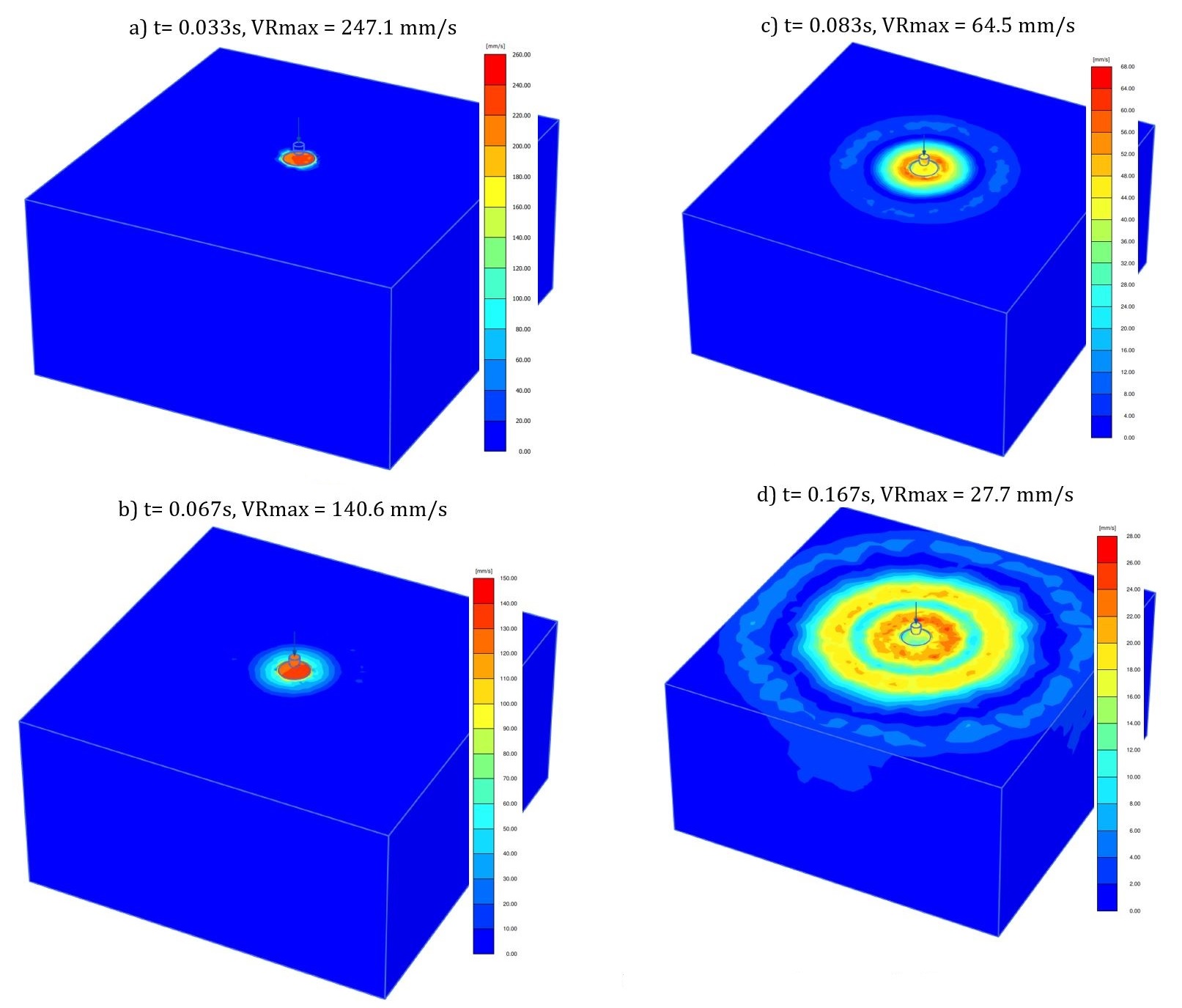
The first model has been prepared taking into account a single blow defined using dynamic loading step with total time duration of 0.5 second. Figure 8.a, b, c and d shows the velocity magnitude propagation at different instances within the total loading duration.
The velocity magnitude distribution in the elastoplastic modelled sand/ silty sand soil, after the first impact showed that surface waves are predominant, the maximum velocity magnitude is founded at the surface. Localized high velocity magnitude under the pounder footprint is observed. Peak velocity magnitude of 247.1 mm/s is observed at the centre of the footprint, then it starts decreasing while moving away from the centre to a maximum value of 4 mm/s at 10m distance at the end of the loading duration. Although the vibration propagation is quite similar for both experimental field and numerical model, however, the calculated VRmax at far distances from the impact point, are considered much lesser than actual vibrations measured during experimental field trial.
The below graph reflects the calculated velocity magnitude exported for a set of nodes at variable distances namely: at centre, 2m, 3m and 10m.
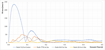
Calculated from Plaxis.
5. 1.2 PLAXIS Multi Blows Simulation Results
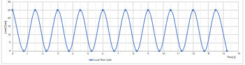
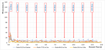
The same loading value has been applied in a periodical sequence allowing for ten cumulative drops, applied on the same simplified model. The loading-unloading sequence was repeated each 1.5 seconds. Graph in figure 9 reflects the loading-unloading sequence in the multi-blows simulation
Following the same behaviour in the single drop simulation, the multi-drops models reflects a localized peak velocity magnitude after the first drop of 140 mm/s located at the centre of footprint, however, this value is much less compared to the one in the single blow. After the first drop, the velocity magnitude was around 26 mm/s and 5.85 mm/s at 3m and 10m distance respectively.
The maximum calculated velocity magnitude drops for the remaining blows to a maximum of 15.2 mm/s, 7.73 mm/s and 4.64 mm/s at the centre of the footprint, 3m and 10m respectively.
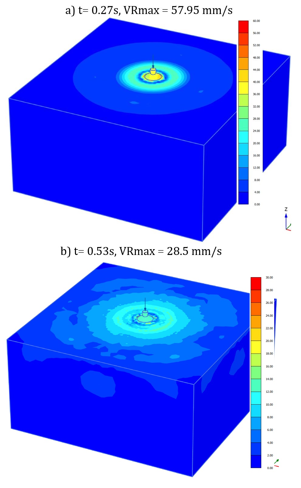
Following contours figures shows the velocity magnitude distribution at 0.27s and 0.53s exported from Plaxis multi-blow model. Figure 11.a & b confirmed that surface waves are considered the main propagating waves resulting from RIC dynamic load on the soil.
Upon completion of the calculation phase, the calculated velocity magnitude has been exported for a set of nodes at variable distances from the centre of impact footprint namely: 0m (centre of footprint), 2m, 3m and 10m.
6. Conclusion
In the present study, a prediction of the vibration induced by rapid impact compaction was presented using a simplified mechanical model developed using PLAXIS software. Mohr-Coulomb plasticity model was used to analyse the constitutive behaviour of the soil under single and multi-blows loading. Spherical propagation of the waves is noticed due to dynamic load application on the loose Sand/ Silty sand soil. The maximum peak ground velocity is noticed at the soil surface at the centre of the footprint.
Although a maximum hammer impact energy has been used in the simulation, the calculated peak ground velocity is less than the one measured during experimental trial.
Depending on the type of nearby structures or utilities, the minimum safe distance shall be maintained to avoid any possible damages caused by vibrations transmitted in the soil induced by RIC dynamic impact. Further developed modelling is required to pre-estimate the velocity magnitude. Field measurements is always required to evaluate the minimum safe distance for a site-specific condition taking into considerations the actual soil behaviour and parameters.
Disclaimer
The current paper is an extent of the conference paper presented on the 5th International on Civil, Structural and Transportation Engineering (ICCSTE’20), November 12-14, 2020, Niagara Falls, Canada.
References
[1] Allen, S. (1996), “The Low Energy Dynamic Compaction of Soil.” Ph.D. dissertation., University of Wales., Cardiff, Wales, UK.
[2] SAICE (2006), “Innovative new ground improvement method uses controlled dynamic compaction.” Civil Engineering.
[3] Serridge, C.J. and Synac, O. (2006), “Application of the Rapid Impact Compaction (RIC) technique for risk mitigation in problematic soils.” presented at IAEG2006, Nottingham, UK, September 6–10.
[4] BRITISH STANDARD, BS 5228-2, Code of practice for noise and vibration control on construction and open sites- Part:2 Vibration, pp 37-38, 2009.
[5] DEUTSCHE NORM DIN 4150-3, “Structural vibration - Part 3: Effects of vibration on structures”, pp 5, 1999.
[6] PLAXIS, Theory Manual.
[7] Kristiansen, H., and Davies, M. , “Ground Improvement Using Rapid Impact Compaction”, presented at 13th World Conference on Earthquake Engineering, Vancouver, 2004.
[8] Kristiansen, H., and Davies, M., “Results of Becker Penetration Testing”, Chilliwack Fire Hall, Final report submitted to Rapid Impact Compactor Ltd., AMEC Earth and Environmental Limited, Burnaby, 2003.
[9] Mitchell, J.K., “Soil improvement: State-of-the-art Report”, Proceeding 10th International Conference on Soil Mechanics and Foundation Engineering, V. 4, Session 12, Stockholm, pp. 509-521, 1981.
[10] Mayne, P.W., “Ground vibrations during dynamic compaction”, Proc of symposium. Vibration Problems in Geotechnical Engineering. (G. Gazetas and E.T. Selig, eds.), ASCE, New York, pp. 247-265, 1985.
[11] BRITISH STANDARD BS 7385-2, Evaluation and measurement for Vibration in Building, Part-2 Guide to Damage levels from Ground borne Vibrations, 1993, pp 2-3.
[12] NOMIS SEISMOGRAPHS. Information from the website. View Article