International Journal of Civil Infrastructure (IJCI)
ISSN: 2563-8084

Volume 4 - Year 2021- Pages 46-54
DOI: 10.11159/ijci.2021.007
Applicability of the AASHTO’s Live Load Distribution Requirements for Integral Bridges
Sami W. Tabsh1, Shehab El Din Mourad2
1American University of Sharjah
P.O. Box 26666, Sharjah, United Arab Emirates
stabsh@aus.edu
22King Saud University
P.O Box 800, Riyadh 11421, Kingdom of Saudi Arabia
smourad@ksu.edu.sa
Abstract - Integral abutment bridges are structures that lack joints and bearings between the superstructure and substructure at their outmost points. They accommodate displacements due to temperature, creep and shrinkage through flexible foundation composed of an abutment wall on single row of piles. Experience has shown that such bridges possess lower construction and maintenance costs, enhanced structural performance, fast construction schedules, and improved vehicular ride-ability. While most design specifications around the world devote ample attention to traditional jointed bridges, they do not adequately cover integral abutment bridges. Hence, this study addresses the issue of whether the current AASHTO LRFD bridge design specifications for live load distribution are applicable to integral abutment bridges. To achieve the objective, single span monolithic bridges are modelled by finite elements with consideration of different girder spacing, free standing pile lengths and wing-wall lengths. The girder distribution factors for flexure and shear from the finite element results are compared with the corresponding formulas in the specifications. The approach utilized by AASHTO to compute the flexural live load effect in the deck slab by considering a unit strip of the slab on rigid supports is checked against the finite element results. In general, findings of the study showed that the AASHTO specifications can be safely used to compute the load effect in girders and deck slab of bridges without joints.
Keywords: Bridges, Deck slab, Finite element analysis, Girder distribution factor, Integral abutment, Live load.
© Copyright 2020 Authors - This is an Open Access article published under the Creative Commons Attribution License terms. Unrestricted use, distribution, and reproduction in any medium are permitted, provided the original work is properly cited.
Date Received: 2020-11-20
Date Accepted: 2020-11-22
Date Published: 2021-03-05
1. Introduction
All structures are supported on the ground by foundation that must ensure stability, serviceability and strength during the useful lifespan. For bridges, the superstructure is carried by abutments and piers, if consisting of multiple spans. Abutments are utilized at the extremities of bridges to provide support between a bridge span and a roadway embankment, resist soil pressure to preserve the required elevation difference and transfer the loads from the span and embankment to the foundation [1]. Structural and geotechnical design requirements for abutments are analogous to those for retaining walls. They must provide stability against overturning and sliding, prevent differential settlement and excessive lateral movements, offer adequate soil bearing or pile load capacity, and possess sufficient shear and flexural strength.
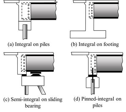
There are different types of abutments, such as: (1) gravity abutment, (2) cantilever abutment, (3) stub abutment, (4) semi-stub abutment, (5) counterfort abutment, (6) spill-through abutment, (7) pile bent abutment, and (8) mechanically stabilized earth system. Depending on the nature of the connection between the superstructure and substructure, the abutment can be considered disjointed, semi-integral or fully integral. Design procedures for each type of abutment may be different because of the way the load is transmitted from the superstructure to the ground [2]. Figure 1 shows schematic diagrams for the most common types of integral and semi-integral abutment bridges without wingwalls.
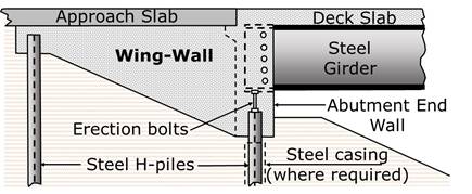
Around the world, there has been increased utilization of integral abutments in bridge construction in recent years. Such bridges have monolithic connection between the superstructure and substructure, which enhances their economy, serviceability and strength [3]. In general, integral abutments are reinforced concrete structural systems consisting of a deep beam rigidly connected to two wing-walls and supported on a single line of vertical piles, as shown in Figure 2. For such a system, the superstructure along with the abutments act as a single structural element. Integral bridges are often classified into four categories, depending on the type of abutment utilized in the structure, which could be of the frame type, flexible support, bank pad, or semi-integral end screen.
When compared to traditional bridges, integral bridges have lower construction and maintenance costs, shorter construction schedule, and simpler construction procedures. They also possess better vehicle riding quality due to lack of expansion joint and require lesser tolerance restriction because of the absence of bearings. For proper performance, some restrictions are imposed by the relevant bridge design specifications and departments of transportations on the bridge total length, skew angle, and in-plane curvature [4]. For example, integral abutments are not preferred when subsoil or embankments are of poor quality and are not suitable in locales where there is high chance of large displacements due to expansion and contraction produced by temperature variations.
There are major differences between the structural behaviour of jointed and integral bridges. Most importantly, abutments supporting a disconnected superstructure are required to resist lateral soil pressure on their own as free standing retaining walls, while integral abutments resist such pressure by shifting it to the superstructure above, which acts as a compression member. The challenges associated with structural analysis, design and construction of integral abutment bridges exist because such structures are not adequately covered in North American specifications and are greatly affected by creep, shrinkage and thermal effect.
2. Literature Review
The current practice in integral abutment bridge construction and design in the United States was documented by Wasserman [5], and compared with the Canadian, Australian and European experiences by Kunin and Alampalli [6], Connal [7] and White [8], respectively. Integral bridge building in Europe was summarized by White et al. in 2010 [9] and more recently in Germany by Pak and Seidl [10]. Previous research on the subject has mainly addressed the thermal load effect [11-13], time-dependent deformations due to creep and shrinkage [14-16], and seismic loading [17-19]. Little published work has considered live load distribution in such bridges, except for the work of Dicleli, Yalcin and Erhan, which is summarized below. Furthermore, previous studies have not addressed the impact of superstructure-to substructure continuity on live load effect within the deck slab in the vicinity of the support.
Dicleli and Erhan [20] compared the live load distribution characteristics of integral abutment with simply supported bridges. They found out that presence of continuity between the superstructure and abutments yields a better distribution of live load effects among the girders compared to bridges that lack continuity, especially in short span bridges. Yalcin and Dicleli [21] studied the effect of the number of girders on the live load girder distribution factors in integral abutment prestressed concrete bridges and corresponding simply supported bridges. Their analysis showed that the impact of the number of girders on shear is minimal. However, as the number of girders increases, the bending moments in the girders of integral bridges significantly reduce whereas the same in simply supported bridges vary within a narrow range. Concerning the impact of the geotechnical properties on live load distribution in jointless bridges, Dicleli and Erhan [22, 23] concluded that soil-structure interaction has a substantial impact on the live load effect within the abutment, but negligible influence on the girders and piles. Also, abutment height was found to have a considerable effect on the live load bending moment in the abutment and piles. Consideration of the effect of backfill behind the abutments resulted in larger superstructure support and abutment moments, but smaller pile moments. Nikravan and Sennah [24] used a computational approach to quantify the effect of abutment continuity on the live load distribution factors in the Canadian Highway Bridge Design Code (CHBDC). Their results confirmed that the live load distribution factors for integral abutment bridges were lower than those obtained from the equations of the code. Hence, correction factors were developed for use with the CHBDC live load distribution factors. With regard to the behaviour of skewed integral abutment bridges under the application of live load, Dicleli and Yalcin found out that trucks that are placed diagonally across the width of the bridge produce the most critical live load effect in bridge components [25]. Yalcin observed that live load distribution of moment and shear effect among the girders is improved in skewed integral abutment bridges compared to simply supported bridges, especially for large skew angles [26]. Correction factors for skewness to be applied to the live load girder distribution factors for nonskewed integral abutment bridges were derived by Dicleli and Yalcin for shear and flexure [27].
3. Problem Statement and Objectives
Experience has shown that bridges containing joints require continuous repairs and restoration because leaking polluted water from the superstructure causes corrosion and spalling in the members below. By removing joints from highway bridges, most of the complications associated with bridge deterioration can be eliminated. As a result, the short-term economy of such bridges is improved due to the use of fewer piles, removal of bearings, elimination of expansion joints and diaphragms and utilization of non-battered piles. In the long-term, bridges without joints will have enhanced durability and longevity. Although integral abutment bridges have been in use for some time in Europe, their coverage in North American bridge design specifications is still limited. For example, the AASHTO LRFD Bridge Design Specifications [28] do not include girder distribution factors (GDF) specifically derived for bridges without joints and do not address the structural analysis of deck slabs in such bridges in the vicinity of integral abutments. Based on the above, the objectives of this study are to:
- Check whether the GDF included in the current AASHTO LRFD Bridge Design Specifications for flexure and shear are applicable to girders supported on integral abutments
- Validate the appropriateness of the approach used in the AASHTO LRFD Bridge Design Specifications for determining bending moments in the deck slab of traditional jointed bridges for integral bridges in the vicinity of the abutments.
This study builds on the earlier published work on the subject by the two authors [29-31] by addressing the adequacy of the live load distribution provisions in the current bridge design specifications when applied to integral abutment bridges.
4. Considered Structures
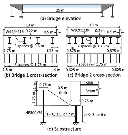
In this study, two different single span composite steel girder bridges with nonskewed integral abutments are considered. The bridges have the same length (25m), abutment dimensions (14 m long, 0.75 m thick, and 2.75 m thick), wing-wall dimensions (3.5 m long, 0.5 m thick, and 1-2.75 m non-prismatic depth), pile lengths (3 m under the abutment wall and 4.75 m under the wing-wall), roadway width (13 m), and material properties (Ec = 25 GPa and Es = 200 GPa). They differ in the concrete slab thickness (220 versus 200 mm), size of steel girders (W920x416 versus W920x239), spacing of girders (3.5 versus 1.75 m), deck slab overhang (1.75 versus 0.875 m), and number of HP300x79 piles (11 versus 12 piles). The effects of changes in the pile length under the abutments (L = 0, 3 and 6 m) and wing-wall length (H = 0, 3.5 and 7 m) on the structural response are also accounted for in the study. Details of the geometry of the superstructure and substructure of the two considered integral abutment bridges are shown in Figure 3.
5. Finite Element Modelling
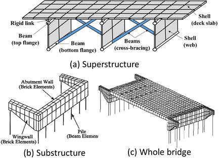
All the integral abutment bridges considered in this research are analysed by a finite element method-based software within the linearly elastic range following to the approach proposed and validated by Tarhini and Federick [32]. Four-node shell elements are used to model the concrete deck slab and steel webs of the girders. Three-node shell elements are also used in the deck slab near the applied wheel loads. Eight-node solid elements are utilized in the wing-walls and abutment walls. The top and bottom flanges of the steel girders and the cross-bracing are modelled by 2-node beam elements. Rigid links are placed between the mid-depth of the deck slab and the centre of the top steel flanges. Instead of considering the soil-structure interaction around the piles, 2-node beams elements are used to model the top portion of the piles, as free standing. The length of the piles is taken as the distance between the bottom of the substructure and the equivalent point of fixity within the soil. Such an approach is reasonable because the piles are often driven at least 6 m into the soil, of which the top 3 m are within pre-augured holes to ensure unrestrained lateral pile movement along the bridge centreline. Figure 4 presents a summary of the finite element modelling of the integral abutment bridges utilized in the study.
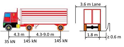
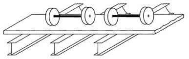
To determine the girder distribution factor for flexure, (GDF) f, from the finite element results, the critical maximum tensile stresses in the top steel flanges due to one, two and three side-by-side HS20 trucks, shown in Figure 5, are considered at the loaded abutment since in a linearly-elastic analysis the normal stress due to flexure is proportional to the bending moment:
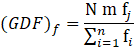
where N = number of loaded lanes, m = AASHTO’s multiple truck presence factor (equal to 1.2 for one loaded lane, 1.0 for two loaded lanes, and 0.85 for three loaded lanes), fj = maximum normal stress in the top flange of the critical steel girder j (MPa), fi = maximum normal stress in the top flange of steel girder i (MPa), and n = number of steel girders within the superstructure.
The corresponding girder distribution factor for shear, (GDF) v, from the finite element analysis is obtained by considering the critical shear stress within the webs of the steel girders at the interface with the loaded abutment:
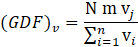
where vj = maximum vertical shear stress in the web of the critical steel girder j (MPa), vi = maximum shear stress in the web of steel girder i (MPa), and all other variables have been defined earlier.
To compute the bending moment per unit strip in the deck slab, M (units: N-mm/mm), from the finite element results, the normal stress at the extreme fibres of the slab is converted to bending moment using the flexure equation from mechanics of materials:

in which the deck slab strip width is represented by the number 1 in brackets, sx = normal stress due to flexure at the top fibres of the slab along a direction perpendicular to the girders (MPa), and t = the deck slab thickness (mm).
6. Results
Results of the critical live load effect in the girders and deck slab from the finite element analysis of the two considered integral abutment bridges with their modifications with respect to the free standing pile length (L = 0, 3 and 6 m) and wing-wall length (H = 0, 3.5 and 7 m) are presented and compared with the relevant provisions in the latest edition of the AASHTO LRFD Bridge Design Specifications [28]. Note that the live load distribution factors in the specifications were derived by Zokaie et al. [33] based on finite element-based structural analyses of jointed bridges that are not built integrally with the supports, and they include multiple truck presence factors.
6.1. Live Load Flexural Effect in Girders
The AASHTO specifications include expressions of girder distribution factors that allow for the determination of the fraction of the live load effect carried by the most critical girder within the bridge when compared with the load effect due to the design truck. Such an approach replaces a complex 3-dimensional modelling by a simple 1-dimensional beam representation. For the case of flexure in an interior girder in a concrete slab-on-girders bridge subjected to multiple side-by-side trucks, the girder distribution factor, (GDF)f, is given by:
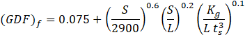
where S = girder spacing (mm), L = span length (mm), ts = deck slab thickness (mm), and Kg = girder stiffness parameter (mm4). The girder stiffness parameter is a function of the slab and girder geometric and material properties, obtained from:

in which Es = modulus of elasticity of the steel girder material (MPa), Ec = modulus of elasticity of the concrete deck slab material (MPa), I = moment of inertia of the bare steel girder about a horizontal axis passing through its centroid (mm4), A = cross-sectional area of the bare steel girder (mm 2), and eg = distance between the centroid of the steel girder and mid-depth of the slab (mm).
Substituting the relevant geometric and material properties of the considered integral abutment bridges in the above equations, one can get the girder distribution factors presented in Table 1.
Table 1. AASHTO’s girder distribution factors for moment.
| Bridge No. |
S
(mm) |
L
(mm) |
ts
(mm) |
Kg
(mm4) |
GDF |
| 1 | 3500 | 25000 | 220 | 2.03x10¹¹ | 0.810 |
| 2 | 1750 | 25000 | 200 | 1.08x10¹¹ | 0.483 |
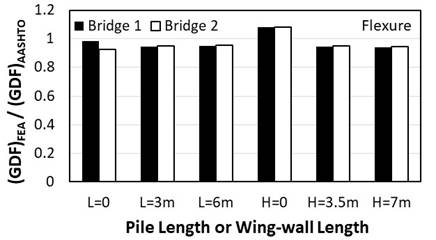
The maximum normal stresses due to flexure in the steel girders of Bridges 1 and 2, with their modifications concerning the pile and wing-wall lengths, from the finite element results are converted to girder distribution factors following the approach presented in the Section 4. The rear axles of the side-by-side HS20 trucks are placed on the bridges in the finite element models at 1 m away from the integral abutment. The girder distribution factors based on the maximum negative bending moment in the most critical interior girder in the computer model are compared with the results obtained from the AASHTO specifications and shown in Table 1. Figure 6 presents the normalized flexural results for Bridge 1 and Bridge 2 with the various modifications, as presented in Figure 3-d. Note that when the free standing pile length takes the values L = 0, 3 and 6 m, the wing-wall length is kept constant at H=3.5 m. Likewise, when the wing-wall length takes the values of H = 0, 3.5 and 7 m, the pile length is kept constant at L=3 m. In general, the findings of the analysis indicate that the AASHTO specifications can reasonably predict (within 7%) the flexural live load effect in the interior girders near the integral abutment for all the cases considered except for the two bridges that do not have wing-walls (H = 0). The reason for this outcome is that such bridges have negligible negative bending moment in the girders at the abutment location due to the rotational flexibility of the support which rests on one row of piles. Hence, such a case is not critical in practice because the capacity of the girders when evaluated based on positive moment at mid-span will be more than adequate to resist such small negative bending moment in the girders at the abutments.
6.2. Live Load Shear Effect in Girders
The AASHTO’s girder distribution factor for the case of shear, (GDF) v, in an interior girder in a concrete slab-on-girders bridge subjected to side-by-side trucks is only a function of the girder spacing, and is given by:

Substituting the relevant girder spacing of the considered integral abutment bridges in the above equation, the girder distribution factors for shear can be obtained, as presented in Table 2.
Table 2. AASHTO’s girder distribution factors for shear.
| Bridge No. |
S
(mm) |
GDF |
| 1 | 3500 | 1.060 |
| 2 | 1750 | 0.659 |
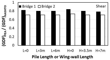
Figure 7 presents the normalized shear load results for Bridge 1 and Bridge 2. The outcome of the analysis shows that the AASHTO specifications over predict (by up to 29%) the shear in the interior girders in such bridges, especially when the girder spacing is small. While the length of the piles and wingwalls slightly impacts the shear live load distribution in the bridges that have large girder spacing, no significant effect of such variables is observed on the bridges that have small girder spacing. The above reported findings on live load distribution within the girders for both flexure and shear agree with previously published results by Dicleli and Erhan [20].
6.3. Live Load Flexural Effect in Deck Slab
In lieu of using a 3-D finite element analysis, the AASHTO LRFD specifications [28] allows the concrete deck in jointed slab-on-girders bridges to be structurally analysed by isolating a unit strip width of the slab perpendicular to the centreline of the bridge at the location of the heavy truck axles and treating the strip as continuous beam on non-moving supports. In this approach, the axles are often transversely placed within traffic lanes on the strip with the aid of influence lines with consideration of the specification’s minimum spacing between the wheels. Depending on the roadway width, single or more side-by-side axles should be considered, with the appropriate multiple presence factors, in order to get the most critical positive and negative bending moments in the interior regions of the slab, as shown in Figure 8. Statics is used for the analysis of the overhang since that part is statically determinate.
In lieu of such an analysis, the specifications includes in an appendix tabulated values for envelopes of maximum positive and negative bending moments per unit strip of the slab for a wide range of girder spacing. For the two considered bridges in this study, the critical live load bending moments, without the dynamic load allowance, in the deck slab provided by the AASHTO specifications are shown in Table 3. Note that AASHTO allows the negative moment in the deck slab to be computed at a distance equal to one-quarter of the top flange length (i.e. b f/4, in which bf is the top flange width) from the centreline of the steel girders. Also, shear in the deck slab is not considered in the AASHTO Bridge Design specifications because experience has shown that such load effect never governs the slab design; hence, it is not addressed in this study.
Table 3. AASHTO’s bending moment in the deck slab.
| Bridge | S(mm) |
Critical M+
(N-mm/mm) |
Critical M-
(N-mm/mm) |
| 1 | 3500 | 26535 | 28913 |
| 2 | 1750 | 16252 | 13519 |
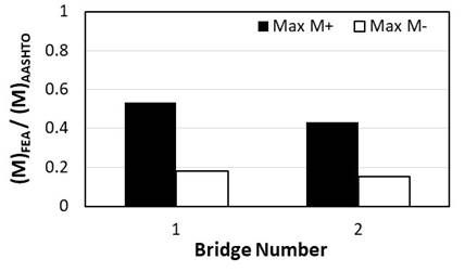
The maximum normal stresses in the transverse direction at the top of the deck slab of Bridges 1 and 2, with their modifications regarding the pile and wing-wall lengths, from the finite element results are converted to bending moments following the method presented at the end of Section 5. The rear axles of the side-by-side HS20 trucks are placed on the bridges in the finite element analysis at 1 m away from the integral abutment. The finite element results showed that the load effect in the deck slab is not greatly sensitive to variations in the free standing pile length or wing-wall length. As expected, they also indicated that there is a large two-way bending action in the deck slab in the vicinity of the integral abutment since the slab is integral with the abutment wall. Figure 9 shows the positive and negative bending moments in the transverse direction of the deck slab normalized with respect to the AASHTO flexural results. As expected, the actual moments in the considered integral abutment bridges are much smaller than those predicted by AASHTO because the load in such bridges is distributed along two perpendicular directions, whereas the AASHTO approach is based on one-way load distribution. The finite element results also indicated large normal stresses in the deck slab along the longitudinal direction (i.e. along the bridge centreline), as a result of membrane action in the slab and negative bending moment in the composite steel girders near the integral abutments.
7. Summary and Conclusions
In this study, typical single span bridges with 25 m spans supported on integral abutments with and without wing-walls are modelled by finite elements with consideration of different girder spacing, pile lengths and wing-wall lengths. The analysis utilizes shell elements in the deck slab and webs of the steel girders, solid elements in the wing-walls and abutment walls, and beam elements in the steel girders flanges, cross-bracing members and piles. The girder distribution factors for flexure and shear in the interior girders from the finite element analysis are compared with values obtained from the expressions provided by the AASHTO Bridge Design specifications. Furthermore, the approach included in AASHTO for computing the flexural live load effect in the deck slab by considering a unit strip width of the slab on rigid supports is checked against the finite element results of the integral abutment bridges. In general, results of this study leads to the following conclusions:
- The AASHTO specifications can reasonably predict the negative bending moment in the interior girders due to live load near the integral abutments. It can slightly over predict the shear in the interior girders in the considered bridges, especially when the girder spacing is small.
- There is a significant two-way bending action in the deck slab near the integral abutments. The two-way action reduces both positive and negative bending moments in the slab along a line perpendicular to the girders when compared with jointed bridges. Hence, the critical flexural live load effect in the slab of the considered integral abutment bridges is much smaller than predicted by the AASHTO specifications, especially for the negative bending moment. In addition to bending moment in the transverse direction, there are normal stresses in the deck slab along the longitudinal direction, as a result of the negative bending moment in the composite steel girders near the integral abutments.
References
[1] P. P. Xanthakos, Bridge Substructure and Foundation Design . Prentice Hall; Facsimile edition, June 30, 1995, 864 pages.
[2] W. F. Chen and L. Duan, Bridge Engineering Handbook: Substructure Design. 2 nd edition, CRC Press, Taylor & Francis Group, 2014, 359 pages. View Article
[3] M. Arockiasamy, N. Butrieng and M. Sivakumar, “State-of-the-art of integral abutment bridges: design and practice,” Journal of Bridge Engineering, Vol. 9, No. 5, September 2004, p 497-506. View Article
[4] M. P. Burke, “Integral Bridges,” Transportation Research Record 1275, TRB, National Research Council, Washington, D.C., 1990, pp. 53–61.
[5] E. P. Wasserman, “Integral Abutment Design - Practices in the United States,” 1st US-Italy Seismic Bridge Workshop, Pavia, Italy, 2007.
[6] J. Kunin and S. Alampalli,“Integral Abutment Bridges: Current Practice in United States and Canada,”Journal of Performance of Constructed Facilities, V14, n3, August 2000, 104-111 p. View Article
[7] J. Connal, “Integral Bridges – Australian and US Practice,”Austroads 5th Bridge Conference, Sydney, Australia, May 2004.
[8] H. White,“Integral Abutment Bridges: Comparison of Current Practice Between European Countries and the United States of America,”Transportation Research and Development Bureau, New York State Department of Transportation, Special Report 152, July 2007, 30 pages.
[9] H. White, H. Pétursson, and P. Collin, “Integral Abutment Bridges: The European Way,” Practice Periodical on Structural Design and Construction, V15 n3, August 2010. View Article
[10] D. Pak, and G. Seidl, “A short history of frame bridges in Germany - From steel frame bridges to integral abutment bridges,” Stahlbau, v 89, n 3, 2020, p 240-249.
[11] W-S Kim and J. A. Laman, “Integral abutment bridge response under thermal loading,” Engineering Structures, v 32, n 6, p 1495-1508, June 2010. View Article
[12] S. Albhaisi, H. Nassif, and E-S Hwang, “Effect of substructure stiffness on performance of steel integral abutment bridges under thermal loads,” Transportation Research Record, n 2313, December 2012. View Article
[13] J. M. Lafave, J. K. Riddle, M. W. Jarrett, B. A. Wright, J. S. Svatora, H. An, and L. A. Fahnestock, “Numerical simulations of steel integral abutment bridges under thermal loading,” Journal of Bridge Engineering, v 21, n 10, October 2016. View Article
[14] M. Arockiasamy and M. Sivakumar, “Time-dependent behavior of continuous composite integral abutment bridges,” Practice Periodical on Structural Design and Construction, v 10, n 3, August 2005, p 161-170. View Article
[15] J. Huang, C. K. Shield, and C. French, “Time-dependent behavior of a concrete integral abutment bridge,” 6th International Bridge Engineering Conference: Reliability, Security, and Sustainability in Bridge Engineering, 2005, p 299-309.
[16] K. Pugasap, W. Kim, and J. A. Laman, “Long-term response prediction of integral abutment bridges,” Journal of Bridge Engineering, v 14, n 2, 2009, p 129-139. View Article
[17] A. N. Kotsoglou, and S. J. Pantazopoulou, “Assessment and modelling of embankment participation in the seismic response of integral abutment bridges,” Bulletin of Earthquake Engineering, v 7, n 2, May 2009, p 343-361. View Article
[18] E. V. Monzon, A. M. Itani, and G. Pekcan, “Seismic behavior and design of steel girder bridges with integral abutments,” Bridge Structures, v 10, n 4, , 2014, p 117-128. View Article
[19] S. Mahjoubi and S. Maleki, “Finite element modelling and seismic behaviour of integral abutment bridges considering soil–structure interaction,” European Journal of Environmental and Civil Engineering, January 2018, p 1-20.
[20] M. Dicleli and S. Erhan, “Effect of Superstructure-abutment continuity on live load distribution in integral abutment bridge girders”, Structural Engineering and Mechanics, v 34, n 5, p 635-662, March 30, 2010. View Article
[21] O. F. Yalcin and M. Dicleli, “Comparative study on the effect of number of girders on live load distribution in integral abutment and simply supported bridge girders”, Advances in Structural Engineering, Multi-Science Publishing Co. Ltd, v 16, n 6, p 1011-1034, June 1, 2013. View Article
[22] M. Dicleli and S. Erhan, “Effect of soil and substructure properties on live-load distribution in integral abutment bridges”, Journal of Bridge Engineering, v 13, n 5, p 527-539, 2008. View Article
[23] M. Dicleli and S. Erhan “Effect of soil-bridge interaction on the magnitude of internal forces in integral abutment bridge components due to live load effects”, Engineering Structures, v 32, n 1, p 129-145, January 2010. View Article
[24] N. Nikravan and K. Sennah, “Parametric model on the CHBDC truck load distribution among girders in single-span integral abutment bridges”, Proceedings of Annual Conference - Canadian Society for Civil Engineering, v 3, January, p 2427-2436, May, 2013.
[25] M. Dicleli and O. F. Yalcin, “Critical truck loading pattern to maximize live load effects in skewed integral bridges”, Structural Engineering International: Journal of the International Association for Bridge and Structural Engineering (IABSE), v 24, n 2, p 265-274, 2014. View Article
[26] O. F. Yalcin, “A comparative study of live load distribution in Skewed Integral and Simply Supported Bridges”, KSCE Journal of Civil Engineering, Springer Verlag, v 21, n 3, p 937-949, March 1, 2017. View Article
[27] M. Dicleli and O. F. Yalcin, “Incorporation of Skew Effects in Live-Load Distribution Factors Developed for Typical Integral Bridges”, Journal of Bridge Engineering, v 23, n 2, February 1, 2018. View Article
[28] AASHTO, LRFD bridge design specifications, American Association of State Highway and Transportation Officials, 8th Edition, Washington D.C., 2017, 1781 p.
[29] S. W. Tabsh and S. Mourad, "Live load distribution in integral composite steel bridges," Engineering Journal, AISC, Volume 35, No. 1, March, 1998, pp. 12-18.
[30] S. Mourad and S. W. Tabsh, “Pile forces in integral abutment bridges subjected to truck loads,” Transportation Research Record, n 1633, p 77-83, Sep 1998. View Article
[31] S. Mourad and S. W. Tabsh, “Deck slab stresses in integral abutment bridges,” Journal of Bridge Engineering, v 4, n 2, p 125-130, May 1999. View Article
[32] K. M. Tarhini and G. R. Federick, “Wheel load distribution in I‐girder highway bridges,” Journal of Structural Engineering, ASCE, Vol. 118, No. 5, May 1992, p. 1285-1294. View Article
[33] T. Zokaie, K. Mish, and R. Imbsen, “Distribution of wheel loads on highway bridges,” Phase III. Final Report No. 12-26(2), National Cooperative Highway Research Program, Transportation Research Record, Washington D.C, 1993.