International Journal of Civil Infrastructure (IJCI)
ISSN: 2563-8084

Volume 4 - Year 2021- Pages 138-143
DOI: 10.11159/ijci.2021.017
Post Tensioned Slab’s Testing Program and Setup
Jasmin Osama Abdelhalim1, Ezzeldin Yazeed Sayed-Ahmed2
The American University in Cairo, Construction Engineering Dept.
New Cairo, Cairo, Egypt.
jasminosama@aucegypt.edu ; eysahmed@aucegypt.edu
Abstract - Post-tensioned slabs are tested in order to investigate the tendon stress at ultimate limit state in case of using bonded and unbonded tendons. The main objective is to compare the values of the mentioned tendon stress to those predicted by ACI 318-19 based on empirical equations for unbonded tendons and based on strain compatibility for bonded ones. The experimental program will be carried on six one-way slabs in four-point flexural loading. Details of the tested slabs and the test set up are presented in this paper. The results of the test carried showed an excellent correlation where almost all of the slabs experimental test results were equal to the theoretical results with a very minor difference around 10 percent. Also, the accuracy of the ACI 318-19 equation for the calculation of the unbonded tendon’s ultimate stress is investigated and the equation has been proven to be accurate.
Keywords: Bonded tendons, prestressed concrete, post tensioned, unbonded tendons.
© Copyright 2021 Authors - This is an Open Access article published under the Creative Commons Attribution License terms. Unrestricted use, distribution, and reproduction in any medium are permitted, provided the original work is properly cited.
Date Received: 2021-06-16
Date Accepted: 2021-06-18
Date Published: 2021-07-12
1. Introduction
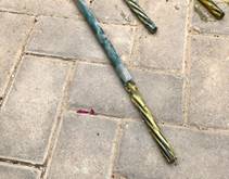
Prestressed concrete has various advantages in comparison to traditional reinforced concrete. Prestressing technique increases the tensile and flexural capacity of the concrete elements in addition to preserving the sustainability concept through the reduction in the usage of materials and sequentially the embodied energy [1-3]. Prestressed concrete elements can be either post- or pre-tensioned: tendons of pre-tensioned elements are stressed before the concrete casting, while in post-tensioned ones, they are stressed after pouring and hardening of concrete. Two types of tendons are used for post-tensioning concrete elements: bonded and unbonded tendons. Bonded tendons (Figure 1) are seven-wires strands inserted inside a plastic or steel duct, and after stressing the strands, grout is injected to fill the duct. Unbonded tendons (Figure 1) are made up of greased seven-wires strands covered with plastic sheathing [2]. Unbonded tendons have many advantages compared to bonded ones such as better corrosion resistance, ease of construction, flexibility and faster construction rate [4].
The major difference between the two types of tendons is the way of stress transfer from the tendon to the concrete, which makes the bonded tendons more widely acceptable in the Egyptian market than the unbonded tendons.

The stress is transferred from the bonded tendon to the concrete via the bond formed due to grouting. Thus, the stress in the tendons can be calculated by the application of the strain compatibility concept. On the other hand, there is no bond between the unbonded tendons and the surrounding concrete due to the presence of the grease and the plastic sheathing [5]. So, empirical equations are adopted by ACI 318-19 [6] provisions to calculate the stress in the unbonded tendons at the ultimate limit state which are given by
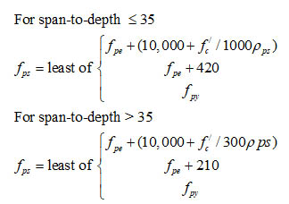
Where, fps is the nominal flexural strength of the unbonded tendon, fpe is the effective prestress of the unbonded tendons, fpy is the yield stress of the tendon, f’c is the concrete compressive strength, ρps is the ratio of the prestressing tendons cross sectional area to the area of concrete section [Aps/ bdp], b is the width of the concrete cross section, and dp is the effective depth of the prestressing tendons.
There is no provision in this code that requires the usage of non-prestressing bonding reinforcement for the bonded systems but a minimum requirement for bonding reinforcement is required for the unbonded system for crack control. The minimum non-prestressed reinforcement is added to the prestressed members with unbonded tendons to provide a flexural behaviour at the ultimate strength rather than the tied arch behaviour. The provided reinforcement limits the crack width and spacing at the service load state when the tensile stresses acting on the prestressed concrete element surpass the concrete modulus of rupture.
According to the ACI 318-19 [6] provisions the nominal strength allowed for the bonded tendons is higher than the nominal strength allowed for the unbonded tendons. This gap could be supplemented by the usage of non-prestressed reinforcement, so the bonded tendons are not on favour over the unbonded tendons as the price of the supplementary non-prestressed reinforcement is less than the grouting price [6].
2. The Experimental Investigation
2.1. The Slab Specimens
The objective of the current research is to investigate the values of the stress in bonded and unbonded tendons at the ultimate limit state and compare these values for unbonded tendons stress to those resulting from the ACI 318-19 [6] equations. An experimental program is designed to test six one-way post-tensioned slabs with bonded and unbonded tendons monotonically to failure under the effect of four-point flexural loading.
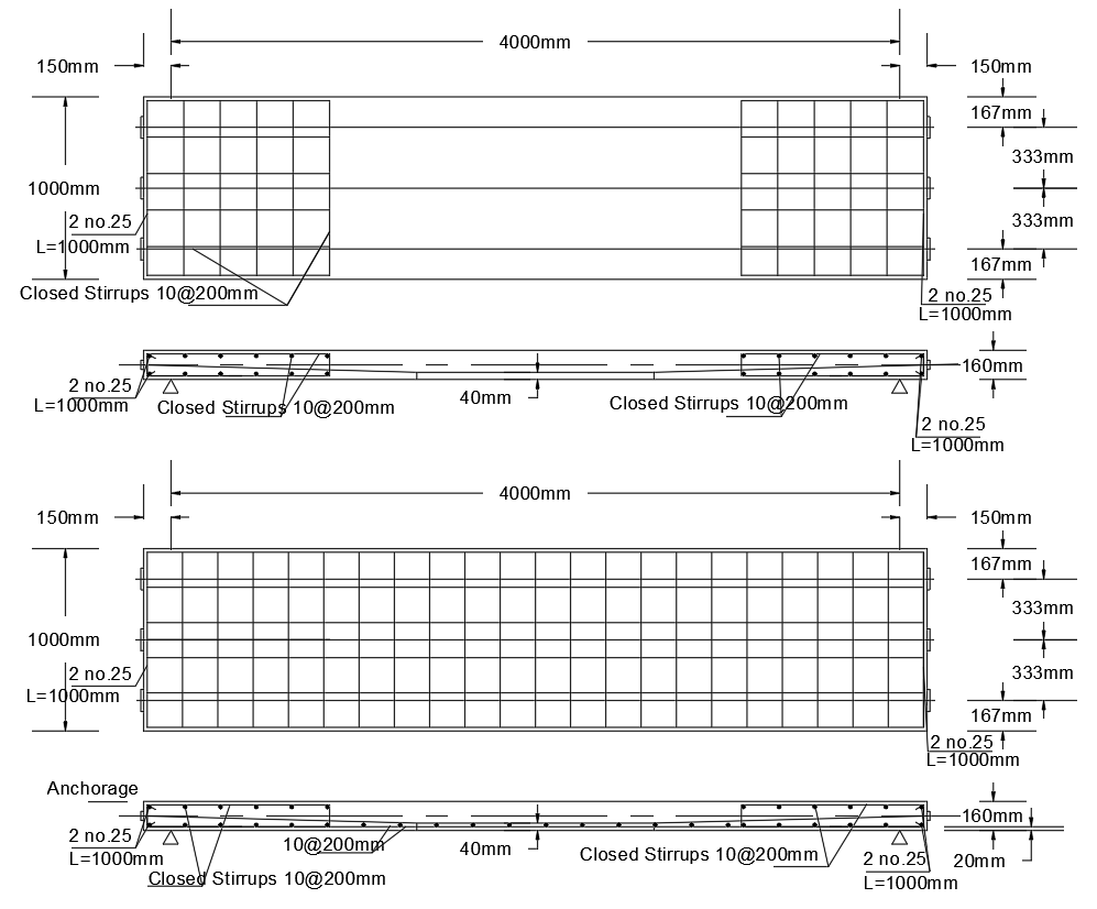
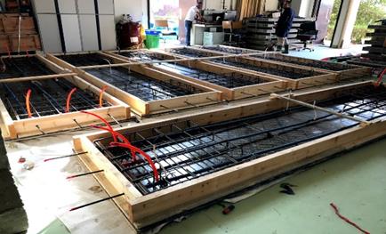
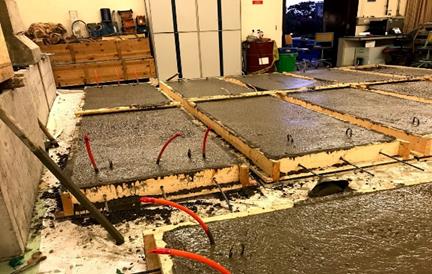
The specimens are chosen of slab type because of the lack of previously carried experimental researches on post-tensioned slab type specimens and due to the wide usage of these slabs in the construction arena. The six specimens are post-tensioned one-way slabs simply supported with span 4.0 meters, width 1.0 meter and thickness 0.16 meters. They are tested under four-point flexural loading. Three sets, each consists of two slabs, are tested. The first set of slabs contains bonded tendons without non-prestressing reinforcement (BS1 and BS2). The second set of slabs contains unbonded tendons without non-prestressing reinforcement (UBS1 and UBS2). The last set of slabs contains unbonded tendons and non-prestressing reinforcement no.10 mm @ 200 mm in the two orthogonal directions according to the ACI 318-19 [6] requirements (UBSR1 and UBSR2). Each slab contains three 12.7 mm diameter seven-wire prestressing strands. The six slabs are designed following the ACI 318-19 [6] provisions with the tendons having double harped profiles and shown in Figure 2. End reinforcement (shown as closed stirrups in Figure 2) is added to the six slabs for resisting stresses produced at the local and general anchorage zones and designed according to the ACI 318-19 [6] provisions. Figure 3 shows the six post-tensioned slab specimens forms with all the reinforcement detailing before concrete casting and after the concrete pouring.
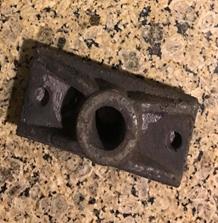
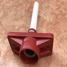
The anchorage system for the bonded slabs is obtained from an Egyptian supplier, Strands-Egypt, while the unbonded anchorage system (Zero void encapsulated system) is imported from GTI-USA. The bonded and the unbonded anchors are shown in Figure 4.
Concrete of compressive strength 30 MPa is intended for the six slab specimens. After the hardening of concrete and reaching compressive strength of average 26.3 MPa after 7 days, the six post-tensioned tendons were stressed: the cubes tested at 7 days of age resulted 23.61, 26.77 and 28.63 MPa.
The jacking force Pj is calculated based on the maximum permissible concrete tensile stresses according to ACI 318-19 [6] provisions which is found to be 459.8 kN. Thus, the prestressing force needed for one tendon is around 154 kN. Tendons prestressing is sequentially performed. The prestressing was done from the “live” end for the six slabs. Table 1 illustrates the elongation measured for the tendons after the application of the hydraulic jack force.
Table 1. The elongation of the tendons after prestressing in mm
|
Specimen |
Tendon no. 1 |
Tendon no.2 |
Tendon no.3 |
|
UBSR1 |
33.5 |
33 |
34 |
|
UBSR2 |
33 |
31 |
32 |
|
UBS1 |
32.5 |
34 |
36 |
|
UBS2 |
34 |
32.5 |
35 |
|
BS1 |
43 |
35 |
36 |
|
BS2 |
34 |
34 |
35 |
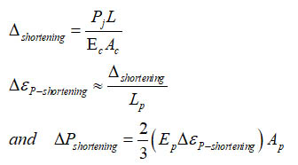
From the elongation of each tendon the strain is calculated, followed by the calculation of the stress in each tendon that is converted to a jacking force giving the following results; and the equations used are the following:
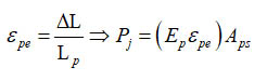
Where, εpe is the tendon’s strain, DL is the tendon total shortening, Lp the tendon length, Pj is the jacking force, E is the Young’s modulus of the tendons steel, and Aps is the tendons cross sectional area. The elongation is obtained from the Table 1, the exact length of the tendon Lp is 4.304 meters and the Young’s modulus of the prestressing tendons Ep is 190,000 MPa. Table 2 illustrates the calculation of the strain in each tendon while Table 3 presents the calculated tendon’s jacking force.
Table 2. Strain calculation in each tendon
|
Specimen |
Strain, tendon 1 |
Strain, tendon 2 |
Strain, tendon 3 |
|
UBSR1 |
0.007783 |
0.007667 |
0.007899 |
|
UBSR2 |
0.007667 |
0.007203 |
0.007345 |
|
UBS1 |
0.007551 |
0.007899 |
0.008364 |
|
UBS2 |
0.007899 |
0.007551 |
0.008132 |
|
BS1 |
0.007667 |
0.008132 |
0.008364 |
|
BS2 |
0.007899 |
0.007899 |
0.008132 |
Table 3. Jacking force calculation in each tendon (KN)
|
Specimen |
Pj tendon 1 |
Pj tendon 2 |
Pj tendon 3 |
|
UBSR1 |
145.95 |
143.77 |
148.13 |
|
UBSR2 |
143.77 |
135.08 |
137.74 |
|
UBS1 |
141.60 |
148.13 |
156.85 |
|
UBS2 |
148.12 |
141.60 |
152.5 |
|
BS1 |
143.78 |
152.5 |
156.85 |
|
BS2 |
148.13 |
148.13 |
152.5 |
2.2. Prestress Losses
The prestressing force losses are calculated according to ACI 318-19 [6] provisions which refers to the Post-Tensioning Institute Manual [3]. The short-term losses are due to elastic shortening, anchorage slippage and friction. While, the long-term losses are due to shrinkage, creep of concrete and relaxation of the tendons. The initial prestressing force (Pi) is thus, the prestressing force after the short-term losses and the effective prestressing force (Pe) is that at the service load stage after all losses. The short-term losses are calculated, starting by the elastic shortening losses, which is given by
Where, Δshortening is the change in length due to the elastic shortening of the concrete slab, L is the slab span, Ec is the modulus of elasticity of the concrete at the initial stage, Ac is the cross sectional area of the slab specimen, Pj is the jacking force, Δεshortening is the change in the tendon strain due to the elastic shortening, Ap is the cross sectional area of the tendon and ΔPshortening is the prestressing force loss due to elastic shortening which is multiplied by 2/3 to account for the sequential prestressing. Table 4 illustrates the values of the prestressing losses due to elastic shortening.
Table 4. Values of shortening losses for each specimen
| Specimen | Δshortening (mm) | Δεshortening |
Δfp-shortening (MPa) |
ΔPshortening (kN) |
|
UBSR1 |
0.57 |
0.000133 |
25.2 |
4.97 |
|
UBSR2 |
0.54 |
0.000126 |
23.9 |
4.73 |
|
UBS1 |
0.58 |
0.000135 |
25.7 |
5.07 |
|
UBS2 |
0.58 |
0.000134 |
25.4 |
5.02 |
|
BS1 |
0.59 |
0.000137 |
26.0 |
5.14 |
|
BS2 |
0.58 |
0.000136 |
25.8 |
5.09 |
The losses due to anchorage slippage are neglected since after prestressing the six slabs, it was detected that no slippage occurred for any tendon. The last source of the short-term losses is the friction losses, which occurs due to the wobble effect and the curvature effect of the tendons with empirical coefficients for the wobble and the curvature losses defined by the PTI manual [3] as k and μ, respectively. For the unbonded tendons μ and k are considered as 0.07 and 0.001, respectively, while for the bonded tendons they are 0.22 and 0.0075, respectively. The prestressing losses ΔPfriction is calculated at the slab mid-span (x = 2.15 m) by
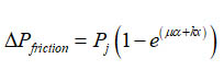
Where α is the angle of tendon curvature in radians. The friction losses due to curvature effect is neglected because the tendon is only inclined by 2o (the tendon is almost straight). The friction losses are calculated for the six slab and the results are presented in the Table 5.
Table 5. Friction losses values for the six specimens
|
Specimen |
Pj (kN) |
Wobble coefficient (k) |
ΔPfriction (kN) |
|
UBSR1 |
437.86 |
0.003 |
2.82 |
|
UBSR2 |
416.60 |
0.003 |
2.68 |
|
UBS1 |
446.58 |
0.003 |
2.87 |
|
UBS2 |
442.23 |
0.003 |
2.84 |
|
BS1 |
453.13 |
0.00246 |
2.39 |
|
BS2 |
448.76 |
0.00246 |
2.37 |
The short term losses for each slab specimen are added in kilo newton and calculated as percentage from the jacking force and presented in Table 6.
Table 6. Six slab specimen's short term losses values
|
Specimen |
Pj (kN) |
ΔPj (kN) |
ΔPj/ Pj % |
Pi (kN) |
|
UBSR1 |
437.86 |
7.79 |
1.78 |
430.08 |
|
UBSR2 |
416.60 |
7.41 |
1.78 |
409.19 |
|
UBS1 |
446.58 |
7.94 |
1.78 |
438.64 |
|
UBS2 |
442.23 |
7.87 |
1.78 |
434.37 |
|
BS1 |
453.13 |
7.54 |
1.66 |
445.60 |
|
BS2 |
448.76 |
7.46 |
1.66 |
441.30 |
2.3. The Transfer Stage
In Table 6, the prestressing force at the transfer stage (considering the short term losses is listed as Pi). Based on this value, the compressive and tensile stresses at outer concrete fibres of the slab mid-span section at the transfer stage is calculated and compared to the limitations defined ACI 318-19 [6] provisions. Based on fʹci = 22 MPa, these limits are -13.2 MPa and 1.17 MPa for the compressive and tensile stress, respectively. The stress at the bottom and top fibres of the mid-section of the slabs are calculated and checked versus the ACI318-19 [6] limits; these are listed in Table 7.
Table 7. Top and bottom stresses for the six slab specimens
|
Specimen |
ftop (MPa) |
ACI 318-19 [6] limit (MPa) |
fbot (MPa) |
ACI 318-19 [6] limit (MPa) |
|
UBSR1 |
-0.53 |
1.17 |
-4.86 |
-13.20 |
|
UBSR2 |
-0.60 |
-4.52 |
||
|
UBS1 |
-0.50 |
-4.98 |
||
|
UBS2 |
-0.52 |
-4.91 |
||
|
BS1 |
-0.48 |
-5.09 |
||
|
BS2 |
-0.50 |
-5.02 |
2.4. Instrumentation and Test Set-Up
Strain gauges are used to measure the change in length at different locations on the concrete and the prestressing tendons. Four strain gauges are fixed on each slab. Three strain gauges are fixed on the slab tendons, while one strain gauge is fixed on the concrete top surface of the slab at the mid-span. Two strain gauges are added on two of the three tendons in each slab at mid-span in order to measure the elongation of the tendons from the start of loading till final failure. The third strain gauge is fixed at the dead end of one of the tendons to detect the long-term losses of the prestressed tendons.
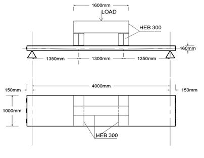
The test setup is designed to test the slab in flexure in a four-point loading fashion. Two line loads are applied on the slabs using two HEB 300 beams, which are supported in the transvers direction of the slab. A third HEB 300, 1.60 m long, is supported on the two HEB 300 parallel to the longitudinal direction of the slab (Figure 5). The length of the 1.60 meters HEB 300 is chosen in order to maintain a trapezoidal bending moment matching the tendon’s harped profile. Rubber pads are positioned between the two HEB-300 and the slab specimen. Linear variable differential transducers (LVDTs) are also used to record the deformation of the slab in the mid-span.
3. Results
The six post-tensioned slabs with bonded and unbonded tendons are tested according to the described procedure and setup and some results are obtained. The flexural capacity of the six slabs were calculated theoretically as according to ACI 318-19 design requirements and procedures and compared to the results recorded during the four-point load flexural testing. Firstly, the difference between the theoretical and experimental values was less than 10 percent confirming the accuracy of the planned program and test setup. Secondly, the unbonded post-tensioned slabs with non-prestressing steel reinforcement showed the highest capacity followed by the bonded post-tensioned slabs, while the least capacity was recorded by the unbonded post-tensioned slabs without non-prestressing steel reinforcement. Also, the current adopted equation by the ACI 318-19 for the calculation of the unbonded tendon’s ultimate stress has proven its accuracy still, the limitation of the equation must be checked.
4. Summary
This paper describes an experimental program designed to test post-tensioned slabs with bonded and unbonded tendons. The slabs are tested in flexure to failure in order to compare the stresses in the bonded and the unbonded tendons to each other and the stresses in the tendons to those calculated based on ACI 318-19 [6] for bonded and unbonded tendons.
The aim of this research is to shed light on the validity of the current equation adopted to calculate the stresses in the unbonded tendons at the ultimate limit state. This test has proved its excellent correlation as almost all of the tested slabs have showed a very minor difference between the theoretical and the experimental results. The detailed results of the test and the comparison between the bonded and the unbonded system in addition to the examination of the validity of the ACI 318-19 code equation for calculating the unbonded tendons ultimate stress will be presented elsewhere.
References
[1] A. A. Abdelrahman, “Applications of Sustainable post-tensioned concrete slabs,” Springer Journal, 2017. View Article
[2] H. Süleymanoğlu, A. Uzel, G. Arslan, “Use of Post-Tensioned Concrete Slabs for Sustainable Design of Buildings,” High Tech Concrete: Where Technology and Engineering Meet, Springer, PP 2390-2395, 2018. View Article
[3] PTI, Post-tensioning manual (sixth edition). Phoenix, AZ, 2006.
[4] B. O. Aalami, (1994) “Unbonded and Bonded Post-Tensioning Systems in Building Construction: A Design and Performance Review,” Pti Technical Notes.
[5] E. Ellobody, C. Bailey, “Behaviour of Unnonded Post-Tensioned One-way Concrete Slabs,” Advances in Structural Engineering, Vol.11, No.1, 2008. View Article
[6] ACI Committee 318. Building Code Requirements for Structural Concrete (ACI 318–2019) and Commentary (ACI 318–2019). American Concrete Institute, 2019.
[7] K. B. Bondy, “Two-Way Post-Tensioned Slabs with Bonded Tendons,” PTI Journal, vol.8, no.2, 2012.