International Journal of Civil Infrastructure (IJCI)
ISSN: 2563-8084

Volume 5 - Year 2022- Pages 95-103
DOI: 10.11159/ijci.2022.013
Settlement Characteristics Due to Excavate Two Parallel Tunnels through a Fill Slope
Xinrong Liu1,2,3, Lojain Suliman1,2,3, Xiaohan Zhou*1,2,3 , Ahmed abd elmageed4
1College of Civil Engineering, Chongqing University, Chongqing 400045, China
2State Key Laboratory of Coal Mine Disaster Dynamics and Control, Chongqing University, Chongqing 400044, China
3National Joint Engineering Research Center of Geohazards Prevention in the Reservoir Areas (Chongqing), Chongqing 400045, China
4National authorities for tunnels
Abstract - The majority of tunneling projects entail designing and building two adjacent tunnels, referred to as twin tunnels. Because the interaction of two parallel tunnels within a slope affects the slope's stability, it's vital to understand the impact of this interaction on the stability. In this paper, the vertical displacement (settlement) of a road above twin tunnels in a fill slope was researched and validated using field measurements. This case study is located in Guizhou province in kaili city in south west of china. The most important part of this study is that the tunnels ‘entrance is in fill soil, which constitutes an unstable body for the tunnel and the slope, especially during excavation. Piles foundation have been used to improve the slope stability. Predictions of settlement were made using the finite element method (FEM) with PLAXIS 3D program, as well as the analytical solution method (new equation). The results appear that the largest displacement was due to the fill entrance. And without the fill, the displacement was too small with non-overlapping shape of displacement. Furthermore, with certain restrictions, the new analytical solution equation is suitable for twin tunnels in a slope.
Keywords: Tunnel; Excavation; PLAXIS 3D; piles; Settlement; fill, FEM.
© Copyright 2022 Authors - This is an Open Access article published under the Creative Commons Attribution License terms. Unrestricted use, distribution, and reproduction in any medium are permitted, provided the original work is properly cited.
Date Received: 2022-08-25
Date Accepted: 2022-08-31
Date Published: 2022-11-04
1. Introduction
The need for better travel facilities in many big cities has been led to pay more attention to the development of tunnels project. Around the world, the population of towns and cities is increasing, thus urban areas need to develop in dense environment.
Many previous scholars have studied induced settlement due to tunnel excavation in a slope. [1] made numerical analysis and model test to analyze the influence of excavating single tunnel in a rock slope, the results show that tunnel excavation cause disturbance to the displacement field of the slope. [2] investigated the impact of building an intersecting new tunnel on an old tunnel in a subterranean environment along a rock slope under 54 circumstances, including tunnel location, backfill presence or absence, and various load magnitudes. The results suggest that a critical interval length must exist between the two tunnel lines. [3] analyzed old tunnels in unstable slope by investigating the behavior of tunnel liner numerically in the context of interaction with the slope. The results focused on relating the reduction of stress in the liner with the increase in convergence. [4] used 2D and 3D finite element and finite difference methods to investigate two tunnels next to a slope and the results related between the plasticity zones around the tunnel and the slope stability. [5] determined the stability of twin tunnels in jointed rock slope and made validation with a project in Himalayas in India and concluded that the invert of the tunnel is more stable than the crown. [6] analyzed a tunnel in unstable slope and concluded that the excavation of tunnels leads to a slope destabilization due to more or less deconfinement of the surrounding rock. However, none of the previous studies mentioned the fill in the slope, which consider a new geological condition and cause excessive deformation and settlement. moreover, there is no detailed researches about twin tunnels interaction in a slope.
In addition, many studies have mentioned the slope and the methods of stabilization ([7], [8], [9], [10]). none of these researches consider the excavation action in a supported slope. Furthermore, there are many studies related to twin tunnels interaction such as ([11], [12], [13]) and many studies related to twin tunnel interaction with another structure such as ([14], [15], [16]). But none of these previous research focused on the interaction between twin tunnels in a slope with other structures. The importance of this research located in investigating the settlement characteristics in a fill supported slope under the excavation action with making comparison with the settlement when there is no support. In this paper PLAXIS 3D software was used to estimate the vertical settlement of the road owing to the twin tunnel excavation using finite element analysis (FEM). In addition to use the analytical solution, which contains a novel equation for predicting twin tunnel settling.
1. Project Description
Building twin tunnels under a road in Guizhou province's Kaili city in southwest China is the case under investigation. The first phase of development began in 2018, and the project opening to the public in 2020. Many slopes run through Kaili city, and tunnels go through them. This case study is one of such tunnels. This town is densely inhabited. As a result, new highways and tunnels are required to vacillate the city's transportation system.
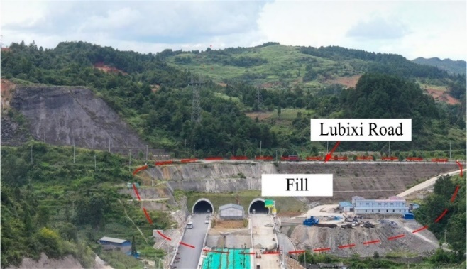
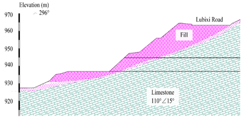
The landform of Luobang Tunnel site is a dissolution-erosion type low-middle mountain landform. The surface is strongly corroded and eroded, and the terrain is undulating. The elevation of the site is 912.0~1121.0 m, and the relative elevation difference is 209.0 m. The entrance of the tunnel is located in the fill of the waste dump. The topography of the tunnel entrance is shown in Fig.1. the geological profile of the case shown in figure (2). The two previous mentioned figure have been taken from the project data.
2. Methodologies involved
2. 1 Finite element analysis FEM
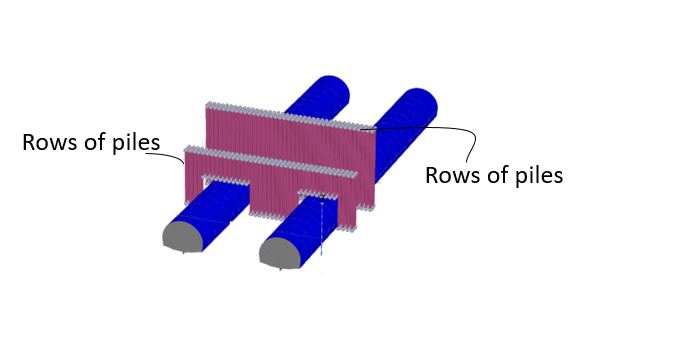
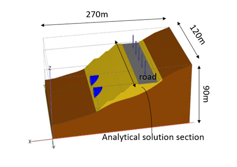
A series of 3D finite element models have been conducted to evaluate the vertical settlement (UZ) due to excavate twin tunnels in many conditions. These conditions have been studied in the parametric study part in addition to analyze the main case study. For the analysis, two major models were utilized: the first, which used pile foundations to make the slope more stable before digging the twin tunnels, and the second, which did not use piles. The piles have been distributed in three rows in the road and three rows in the slope above the tunnels as shown in figure (3). The distance between the piles was 1.5m in each direction. The piles material consists of steel from the outside and grout inside it. The characteristics of piles appear in table (1). While the soil parameters are shown in table (2). FEM model has been shown in figure (3).
Table 1. Pile characteristics
|
E (KN/m2) |
γ(KN/m3) |
D(m) |
|
59000000 |
59 |
0.108 |
Table 2. Geotechnical parameters for simulation process
|
material |
C (kN/m2) |
Ф(degree) |
E (kN/m2) |
µ |
γ(kN/m3) |
|
Fill |
24 |
10 |
30000 |
0.4 |
18 |
|
Rock |
200 |
30 |
600000 |
0.2 |
24 |
(a) 3D model configuration with piles
b) 3D model configuration
2.2 analytical solution (new equation)
The superposition technique is recommended for estimating settling caused by twin tunnel excavation. In this approach, the settlement prediction is based on a single-tunnel prediction formula. The diameter, size and depth of the second tunnel is assumed to be the same as the first tunnel. This analytical formula contains two types of settlement: uniform convergence and vocalization as appear in figure (4). These two types have been summed to be adopted for twin tunnels.
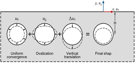
Convergence mode:
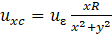
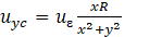
Ovalization mode:


Where: R: the radius of the tunnel, H: the tunnel depth to the spring line, µ: The Poisson’s ratio, X: the vertical distance of the section. : max.deformation due to ovalization occurs at the tunnel cavity. : max.defo-rmation due to convergence occurs at the tunnel cavity. Y: the horizontal distance of the section. Based on the superposition principle, the settlement for two tunnels could be expressed as the following:


Where: Uy1:(UY1=Uyc+Uyo): th the first tunnel’s vertical settlement (mm), Uy2:(UY2=Uyc+Uyo) the second tunnel’s vertical settlement (mm), Uyc: Settlement due to the convergence mode (mm), Uyc: Settlement due to the ovalization mode (mm), Ux1: (Ux1=Uxc+Uxo): the first tunnel’s horizontal settlement (mm), UX2: (Ux2=Uxc+Uxo): the second tunnel’s horizontal settlement (mm), Uxc: Settlement due to the convergence mode (mm), Uxo : Settlement due to the ovalization mode (mm).
3. Results and Parametric study
The results include two main parts, the first part is general results for the main case, a comparison between excavating the tunnel in supported and unsupported slope, and using rock instead of fill to investigate the effect of fill on the settlement value and shape, moreover the analytical solution has been used to verify the numerical analysis results (FEM). The second part is a parametric study includes.
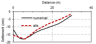
3.1. Validation of numerical results with site
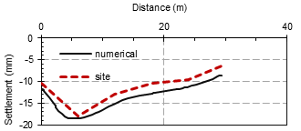
To evaluate the reliability of the simulations, the vertical displacements(settlement) of the left tunnel and the right tunnel are obtained from field measurements. Many researches have been carried out for a long time to compare numerical simulation findings with measurements on full-scale geotechnical structures. As a result, completing the validation process is critical in order to validate the model's ability to address issues.
This verification was in the road above each tunnel during the excavation. The most significant aspect of this validation is that the simulation's maximum settlement matches the maximum settlement in the field, as illustrated in figure (5). The field measurements from the site obtained by putting many instrumentation during the excavation in six monitoring points. The maximum settlement in both tunnels were more than 15mm.
(a). left tunnel
(b) right tunnel
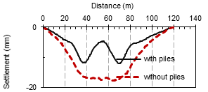
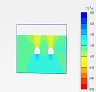
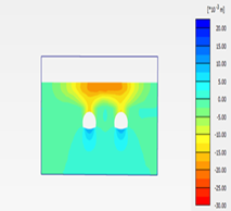
3.2 The difference in settlement characteristics with and without piles
The piles seem to have reduced vertical displacement in several locations, according to the findings. Not only the vertical displacement values have been reduced, but the settlement overlaps have also been eliminated. Figure 6 depicts the difference in vertical settling when piles are presented vs when they are not. In the presence of piles, the highest settlement value was 1.2cm. while in absence of piles the maximum settlement reached to 1.8cm. Figure (7) shows the difference in the contour settlement in wo cases which are: (1) the presence of piles. (2) no piles. It is clear from the two figures that the presence of piles cause separation of the settlement. While, whereas no piles the settlement are overlapped. In addition, the piles made the maximum settlement concentrate in a small area above each tunnel.The piles seem to have reduced vertical displacement in several locations, according to the findings. Not only the vertical displacement values have been reduced, but the settlement overlaps have also been eliminated. Figure 6 depicts the difference in vertical settling when piles are presented vs when they are not. In the presence of piles, the highest settlement value was 1.2cm. while in absence of piles the maximum settlement reached to 1.8cm. Figure (7) shows the difference in the contour settlement in wo cases which are: (1) the presence of piles. (2) no piles. It is clear from the two figures that the presence of piles cause separation of the settlement. While, whereas no piles the settlement are overlapped. In addition, the piles made the maximum settlement concentrate in a small area above each tunnel.
 |
 |
|
The settlement in the road with piles |
The settlement in the road without pile |
|
|
Figure (7). The difference in the contour settlement with and without piles. | ||
3.3 Verification the numerical results by analytical solution method
The analytical solution has been used to make verification with the numerical one (FEM) analysis. Two sections have been considered, the first one is directly above the tunnel, the second is 4m above the twin tunnels. According to the previously mentioned formula, the value of settlement seems to be almost the same as the finite element method. Still there is deviation in the centerline of the tunnel in the numerical simulation as appear in fig 8, which leads to consider that this relation is applicable for twin tunnels in a slope with considering the deviation. The parameters which have been used in the analytical equation are the average of the parameters that have been shown in table (2) along the height of the slope.
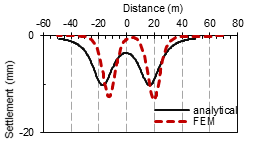
directly above the tunnel
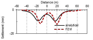
4m above the tunnel
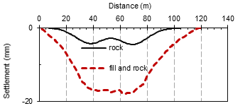
3.4. Rock instead of fill
As previously mentioned, the location of fill in the tunnel's entrance was the most notable geological feature. Instead of fill soil, rock of limestone similar to the first soil layer was used to study the impact of fill soil. Fig. 9. Shows that the rock converts the shape of displacement from (v) shape to (w) shape.
3.5 Parametric study
Three major parametric studies have been carried out. The first included changing the distance between the two tunnels. The second was about the sequence of excavation, the third includes soil parameters variation such as the modulus of elasticity (E), the cohesion (C) and the friction angel.
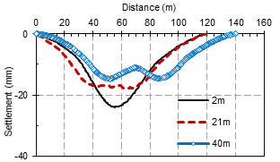
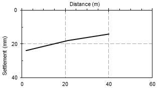
3.5.1 Effect of The distance between two tunnels
In this case study, the distance in the site between the two tunnels was 21m, then two distances have been made 2m and 40m. The results appear in figure (10). The results show that with increasing the distance the displacement in the road has been decreased. Also when the distance has increased the shape of the settlement will be different because of preventing the overlapping in the settlement. Thus, it can be concluded that with increasing the distance between twin tunnels the (v) shape of settlement will convert to (w) shape. Figure (11) shows the variation of the maximum settlement with the distance variation.
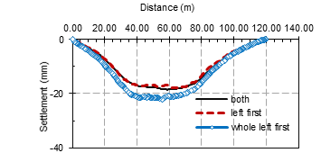
3.5.2 Sequences of excavation
The first 25 meters of the left tunnel have been dug at the site, and the excavation of the following tunnel has begun. The two major examples in this parametric research are: constructing both tunnels at the same time, excavate the whole first tunnel then the whole second tunnel, in addition to the main case which is excavate the first 25m of the first tunnel then excavate both at the same time. The results are shown in figure (12).
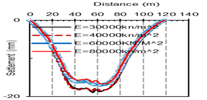
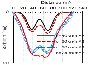
3.5.3 Modulus of Elasticity, cohesion and friction angel
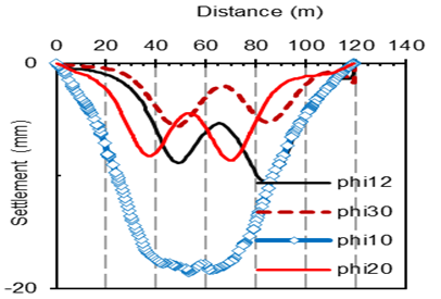
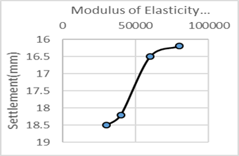
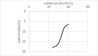
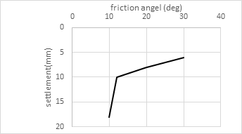
For the fill soil, various values of the modulus of Elasticity (E), cohesion (C), and friction angel (phi) were employed in this parametric research, to know the impact of these values on the shape and values of displacement on the road. The results shown in the following figures. Based on the three distinct soil characteristics, it appears that the variation of friction angel and cohesion affect the settlement value and shape (convert the settlement shape from U shape to W shape), The elasticity modulus, on the other hand, affects the settlement value but not the shape. In both figures (13 and 14) it can be note that with increasing the modulus of elasticity and cohesion the vertical displacement will decrease. However, increasing cohesion has a greater impact on settling value than the modulus of elasticity. figure (15) illustrates how the friction angle affects the form and values of the settlement. The figures (16-18) shows the maximum settlement with the (modulus of elasticity, cohesion and friction angel).
Discussion
In Figure (19), several factors were examined in order to find the most effective influence on the settlement shape and value. It appears that the distance between the two tunnels which was 2 m has a greater impact on road settling more than any other factors, due to the high degree of interaction between the two excavated tunnels, and the value of settlement was more than 2 cm. When using rock instead of fill, the amount of settlement is reduced to less than 0.5 cm. According to Figure (19), increasing the cohesiveness of the fill soil causes minor settlement. As a result, embedding the whole model in rock results in the lowest amount of settling. The second element that reduced the settlement was growing cohesiveness. This confirms what has already been stated: the fill was the primary source of the slope's settlement, and without it, the displacement would be less. The purpose of using E=30000kn/m2 and then E=40000kn/m2 was to show that the range of settlement would not be very different if the values were closer together. While when we take E=40000kn/m2 then E=60000kn/m2 the range of settlement will be more. Also from the chart it appears that after E=60000kn/m2 the settlement will be the same. It is self-evident that increasing cohesion values has a greater impact on settling than increasing the modulus of elasticity. Table (3) shows the effect of each parameter on the settlement shape.
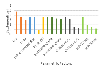
Table (3). The effect of the parameters on the settlement shape
|
C=24 |
C=30 |
C=36 |
C=40 |
Phi=10 |
Phi=12 |
|
U |
W |
W |
W |
U |
W |
|
Phi=20 |
Phi=30 |
E=30000 |
E=40000 |
E=60000 |
E=80000 |
|
W |
W |
U |
U |
U |
U |
|
2m |
21m |
40m |
Only rock |
Rock and fill |
|
U |
U |
W |
W |
U |
According to the previous mentioned points related to the parameters which affect the settlement values and trough and for other projects which include the same description it can be concluded that controlling the distance between the twin tunnels can reduce the settlement to a reasonable value. However, the distance between twin tunnels depends on the geographical conditions and the allowable area. In general, increasing the distance will reduce the degree of interaction.
Conclusion
The impact of the execution twin tunnels on the settlement trough and values is shown in this paper. the results of numerical model are calibrated based on the measured data from site.in addition, the numerical results have been verified with analytical solution method which includes new equation to predict the settlement. moreover, this paper includes main case and a parametric study which includes many conditions. the following conclusions can be obtained:
- Using piles during the excavation of twin tunnels in a slope prevents settlement overlaps.
- The fill makes the settlement between the two tunnels overlaps, while when replacing the fill in rock, the displacement was smaller and the overlaps between the settlements of the two tunnels decreased.
- The cohesion and friction angel affects the value of settlement and the settlement trough (overlapping) more than the modulus of elasticity.
- The most effective factors which increases the settlement was the closest distance between the tunnels which was 2 m, because it permits large interaction.
- Using the analytical solution to verify the numerical results gives good agreement.
- The analytical solution may be utilized in practical engineering to estimate settlement above twin tunnels on a slope while taking the tunnel centerline deviation into account.
- MC model for rock simulation shows good agreement with site readings.
Acknowledgments
This work was supported by the National Key R&D Program of China (Grant No. 581 2018YFC1504802), National Natural Science Foundation of China (Grant No.41972266) and Chongqing Postdoctoral Natural Science Foundation of China (Grant 582 No. cstc2019jcyj583 bshX0072).
References
[1] Zhang, Qian, Jing Wang, Wenyu Wang, Songsong Bai, Peng Lin. 2019 Study on slope stability due to the influence of excavation of the high-speed rail tunnel. Geomatics, Natural Hazards and Risk 10(1):1193-1208. View Article
[2] He, Ziyong, Chao Li, Qiao He, Yang Liu, Jiangong Chen. 2020 Numerical Parametric Study of Countermeasures to Alleviate the Tunnel Excavation Effects on an Existing Tunnel in a Shallow-Buried Environment near a Slope. Applied Sciences 10(2):608. View Article
[3] Causse, Lionel, Roger Cojean, and Jean-Alain Fleurisson 2015 Interactions Between Tunnels and Unstable Slopes: Role of Excavation. In Engineering Geology for Society and Territory-Volume 2. Pp. 237-242: Springer. View Article
[4] Vlachopoulos, N, I Vazaios, and BM Madjdabad 2018 Investigation into the influence of excavation of twin-bored tunnels within weak rock masses adjacent to slopes. Canadian Geotechnical Journal 55(11):1533-1551. View Article
[5] R. Das, P. Singh, A. Kainthola, S. Panthee, and T. Singh, "Numerical analysis of surface subsidence in asymmetric parallel highway tunnels," Journal of Rock Mechanics and Geotechnical Engineering, vol. 9, no. 1, pp. 170-179, 2017. View Article
[6] L. Causse, R. Cojean, and J.-A. Fleurisson, "Interactions Between Tunnels and Unstable Slopes: Role of Excavation," in Engineering Geology for Society and Territory-Volume 2: Springer, 2015, pp. 237-242. View Article
[7] Li, J, L. G. Tham, S. M. Junaideen, Z. Q. Yue. 2008 Loose fill slope stabilization with soil nails: full-scale test. Journal of geotechnical and geoenvironmental engineering 134(3):277-288. View Article
[8] Zhou, YD, CY Cheuk, and LG Tham 2009 Numerical modelling of soil nails in loose fill slope under surcharge loading. Computers and Geotechnics 36(5):837-850. View Article
[9] Chen, H, CF Lee, and KT Law 2004 Causative mechanisms of rainfall-induced fill slope failures. Journal of geotechnical and geoenvironmental engineering 130(6):593-602. View Article
[10] Cheuk, CY, CWW Ng, and HW Sun 2005 Numerical experiments of soil nails in loose fill slopes subjected to rainfall infiltration effects. Computers and Geotechnics 32(4):290-303. View Article
[11] A. Golshani, M. Varnusfaderani, and S. Poorhashemi, "Effect of excavation stages and lining sequences on ground settlement in a twin tunnel," in Tunnels and Underground Cities: Engineering and Innovation meet Archaeology, Architecture and Art: CRC Press, 2019, pp. 5638-5647. View Article
[12] M. Nematollahi, H. Molladavoodi, and D. Dias, "Three-dimensional numerical simulation of the Shiraz subway second line–influence of the segmental joints geometry and of the lagging distance between twin tunnels’ faces," European Journal of Environmental and Civil Engineering, vol. 24, no. 10, pp. 1606-1622, 2020. View Article
[13] N. A. Do, D. Dias, T. T. Vu, and V. K. Dang, "Impact of the shield machine’s performance parameters on the tunnel lining behaviour and settlements," Environmental Earth Sciences, vol. 80, no. 16, pp. 1-13, 2021. View Article
[14] M. Nematollahi and D. Dias, "Interaction between an underground parking and twin tunnels–Case of the Shiraz subway line," Tunnelling and Underground Space Technology, vol. 95, p. 103150, 2020. View Article
[15] S. Li, P. Li, M. Zhang, and Y. Liu, "Influence of approaching excavation on adjacent segments for twin tunnels," Applied Sciences, vol. 10, no. 1, p. 98, 2020. View Article
[16] M. A. Soomro, "3D finite element analysis of effects of twin stacked tunnels at different depths and with different construction sequence on a piled raft," Tunnelling and Underground Space Technology, vol. 109, p. 103759, 2021. View Article