International Journal of Civil Infrastructure (IJCI)
ISSN: 2563-8084

Volume 6 - Year 2023- Pages 17-26
DOI: 10.11159/ijci.2023.003
Development of Relative Rigidity Measure for Shallow Foundations
Sami W. Tabsh1, Magdi Elemam1
1American University of Sharjah, Department of Civil Engineering
jeniffer.viegas@tpf.pt
Sharjah, United Arab Emirates
stabsh@aus.edu; melmam@aus.edu
Abstract - This study investigates the influence of the structure-to-soil relative rigidity on the structural behaviour of shallow foundation. The effect of change in the material and geometrical properties on the critical soil pressure intensity, bending moment and shear force of spread footings and rafts is investigated numerically using the finite element method. The parameters that are addressed in the analysis include the foundation thickness, soil modulus of subgrade reaction, concrete modulus of elasticity and plan geometry of the foundation. The foundation is modelled by thick shell elements while the soil by Winkler elastic springs. Findings of the study showed that the most important variables that affect the structural response of shallow foundations are the thickness and plan dimensions of the foundation, and to a lesser extent the soil modulus of subgrade reaction and concrete modulus of elasticity. A relative foundation-to-soil rigidity measure that can quantitatively predict the degree of stiffness of a shallow foundation was developed. The rigidity measure can help engineers in forecasting whether the traditional rigid foundation approach can be safely used to analyse a given spread footing or raft.
Keywords: Finite element analysis, Foundation, Mat; Modulus of subgrade reaction, Raft, Soil-structure interaction, Spread Footing.
© Copyright 2023 Authors - This is an Open Access article published under the Creative Commons Attribution License terms. Unrestricted use, distribution, and reproduction in any medium are permitted, provided the original work is properly cited.
Date Received: 2023-03-23
Date Revised: 2023-04-28
Date Accepted: 2023-05-01
Date Published: 2023-08-01
1. Introduction
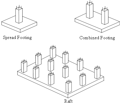
A shallow foundation is a concrete structure that is buried very close to the surface of the ground with the objective of transferring loads from columns and walls of the superstructure to a wide area within the soil. It takes different forms, such as spread footing, combined footing, or raft, as shown in Fig. 1. Spread or isolated footings are reinforced concrete pads that support concentrated loads coming from individual columns. They are efficient in resisting loads, cost effective to build, and easy to construct by nonskilled workers. Raft or mat foundations are relatively thin reinforced concrete slabs that carry the entire load of a structure and distribute it to a large area of soil under its footprint. They can be either conventionally reinforced or post-tensioned, and are effective in limiting differential settlement and suitable for watertight construction below the water table [1].
Traditionally, a shallow foundation is approximately analysed by assuming it infinitely rigid, irrespective of the material properties of the foundation structure and supporting soil; thus, eliminating the interaction between them [2]. Such an assumption greatly simplifies the analysis because it leads to uniform soil pressure underneath the foundation. Critical bending moments and shear forces along the two major axes of the foundation can then be approximately computed using a variety of different methods. For the case of spread footings, a part of the footing is isolated and critical bending moment at the face of the column and shear at some distance away from the column can be obtained from the equations of equilibrium. For rafts, the internal load effect within the raft method can be calculated using statics by taking strips of the raft along the columns in the longitudinal and transverse directions of the raft. More accurately, the critical shear and moment values can be obtained by formulas based on elastic analysis, such those of the direct design method or the two-way slab panel formulas. If the columns planted on the raft do not have uniform spacing or do not line up along a straight line, then the equivalent frame method can be used; in that case, the statistically indeterminate frame will need to be analysed by a method, such as the moment distribution. Once the critical internal shear forces within the raft are calculated, the thickness of the foundation is determined such that one-way and two-ways action shears do not govern since spread footings and rafts are not typically reinforced with stirrups in the transverse direction. Longitudinal steel reinforcement along both major directions at the bottom of a spread footing and at the top and bottom of a raft are then computed based on the magnitude of the critical bending moments. The flexural reinforcement must also be checked against the temperature and shrinkage code requirement and increased if needed.
However, assuming the soil bearing pressure under a shallow foundation constant or linearly varying is not always a conservative assumption, as it does not only influence the serviceability limit state but also affect the structural safety of the foundation. In some cases, nonuniform soil bearing pressure distribution can cause more critical internal bending moments and shear within the foundation than those resulting from assuming uniform soil pressure underneath it. Consequently, incorrect calculation of the load effect within the foundation can directly affect the thickness selection and longitudinal steel reinforcement.
2. Objective and Scope
The objective of the study is to derive a relative rigidity factor for shallow foundations that can judge whether a spread footing or raft can be safely analysed using the rigid foundation analysis approach. To do that, a sensitivity analysis is first employed to investigate the extent of influence of various geometric and material properties on the structural response of shallow foundation. The variables that are considered in the study are the foundation thickness, soil modulus of subgrade reaction, modulus of elasticity of concrete and plan geometry of the foundation. The considered limit states are the maximum and minimum soil bearing pressure, critical bending moments, and maximum shear. The approach used to address the stated objective utilizes the linearly elastic finite element method to analyse the foundation twice, once by considering the flexibility of the foundation and another time by ignoring it. The soil bearing pressure and load effect within the flexible foundation are then examined and compared to those of a corresponding rigid one.
3. Previous Research
Examination of previously published research on soil bearing pressure distribution and load effect in shallow foundations suggests that the relative rigidity of the foundation with respect to the soil is dependent on many parameters with varying extent. Among these parameters are the foundation thickness and modulus of elasticity of the concrete, soil Poisson ratio and modulus of subgrade reaction, plan geometry of the foundation, cross-section dimensions of the columns carried by the foundation and stiffness of the supported superstructure.
With respect to past research on the analysis of spread footings, design aids and numerical solutions for rigid rectangular footings subjected to axial loads and biaxial bending are available in the literature [3,4]. Houlsby and Cassidy [5] investigated circular-shaped footings by employing a plastic model of the soil that is based on equilibrium conditions, assumed soil pressure distribution, and maximum soil bearing capacity. Gourvenec et al. [6] used the finite element approach to study the uniaxial vertical bearing capacity of rectilinear footings on homogeneous undrained clay with the help of Tresca and von Mises soil models. Kumar and Ghosh [7] studied the ultimate bearing capacity of two interfering strip footings by using the method of stress characteristic, in which the analysis was performed by choosing two different possible failure mechanisms. Yamamoto et al. [8] proposed two semi-analytical formulas for the design of shallow foundations on compressible sands that use one-dimensional compression model and the concept of “bearing modulus.”. Bouassidaet al. [9] determined lower bounds on the bearing capacity of a rigid foundation on a soil reinforced by a group of floating columns using limit analysis in terms of a dimensionless factor that depends on the characteristics of the soil and the inclusion, the area replacement ratio, the columns length, and a uniform surcharge surrounding the foundation. More recently, Rodriguez-Gutierrez and Aristizabal-Ochoa [10] developed a simplified analytical method that determines the axial load and biaxial moment capacities of a rigid spread footing of regular or arbitrary shape resting on soil with consideration of either uniform, linear or parabolic pressure distribution at the soil-footing interface.
With regard to previous research on the analysis of rafts, Teli et al. [11] investigated the impact of raft rigidity and soil properties on the response of the foundation of a multi-storeyed structure. They found out that modulus of subgrade reaction has higher influence on the soil bearing pressure as compared to flexural rigidity of raft. While the rigidity of the foundation highly influences the shear stress and bending moment in foundation, the effect of variation in the soil properties on structural design of the foundation is insignificant. Gong et al. [12] used model tests to demonstrate that when raft thickness is larger than one-sixth the span between columns, the rigidity of frame structure with raft foundation can be large enough to cause linear distribution of contact soil pressure on the foundation and the settlement can be calculated using elastic theory in combination with the principle of superposition. Alshorafa [13] studied the rigidity of raft foundation following theoretical and experimental approaches. He used the results to adjust the column loads and soil pressure under the raft to correct the shear and bending moment in the foundation that are obtained by the rigid foundation approach. Findings of the study showed that the critical moments obtained from the modified conventional rigid method are between those obtained by the conventional rigid method and the finite element procedure. Çekinmez [14] used the finite element software PLAXIS 3D to determine the effect of column spacing, stiffness of the soil and thickness of the foundation on the soil/foundation contact stress distribution, settlement distribution, scattering of modulus of subgrade reaction of a raft foundation. Results of the study are used to develop a relationship between size of the foundation, deformation modulus of foundation soil and modulus of subgrade reaction. The modulus of subgrade reaction is nonuniform for stiff rafts, loaded by columns having large spacing and supported on stiffer subgrade soils. Pillay [15] compared the analysis results of rafts using the conventional, Winkler, and continuum methods. He found out that the conventional rigid method under-estimated the negative bending moment values for rafts supported on weak soil. Field observations revealed that cracking pattern corresponds well with those from continuum analysis. The Winkler method often gives overly conservative results. The combined model that incorporates the superstructure with the raft yields comparatively less absolute and differential settlements due to the levelling effect of the stiff superstructure.
The current study builds on the previously published research by the first author on spread footings [16] and extends the recent work of the two authors on raft foundation [17,18].
4. Finite Element Model
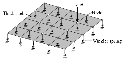
The shallow foundation in this study is analysed within the elastic range by the finite element method using the software SAFE [19,20]. SAFE is a single user interface that enables modelling, analysis and design of foundations, basements, and floors. The analysis engine of SAFE translates the object-based model into a finite-element model by managing the tessellation process with object orientation, observing bounds to establish effective aspect ratios, and connecting mismatched mesh seams. The software can analyse structures within the elastic and inelastic bounds, considering either static or dynamic behaviour. The foundation is modelled within the linearly elastic range by thick shell elements formulation that follows Mindlin/Reissner, which accounts for shear deformations but has no effect on membrane (in-plane) behaviour. The underlying soil is modelled by discrete elastic Winkler springs at the nodes that do not carry tensile forces and their stiffness is determined by the soil’s modulus of subgrade reaction and mesh size. The foundation optimum mesh size of 0.5 m × 0.5 m was chosen following a sensitivity analysis that considered square meshes ranging between 0.25 m and 2 m, with the aim of having a balance between the computational time and accuracy of the results [18]. In order to simplify the analysis, the loads on the raft are applied through the columns based on their tributary. In this approach, the corner and the edge columns are subjected to one-quarter and one-half of the load on the interior column, respectively. Details of the finite element model are shown in Fig. 2.
5. Approach
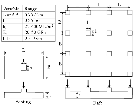
To determine the effect of a shallow foundation’s design parameter on the soil-structure interaction and structural response, two case studies comprising of a spread footing and raft foundation are addressed. The considered spread footing is either square or rectangular (with a length-to-width ratio L/B=1-2) and subjected to a concentric load at its centre. The raft is symmetrical, consisting of 3 bays by 3 bays, where the spacing between the columns along the two principal directions is equal. The load on the raft is applied through the 16 columns, in which the intensity is proportional to the tributary areas they serve. The range of the considered geometric dimensions and material properties are presented in Fig. 3, together with the plan and elevation views of the two foundations. The Poisson’s ratios for the involved materials are kept constant, equal to 0.2 for uncracked concrete and 0.3 for the soil.
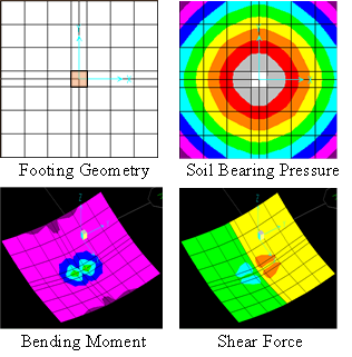
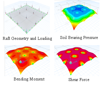
Figures 4 and 5 show the geometry and results of analysis for typical square spread footing and 3 bays by 3 bays raft, respectively. The footing is 3mx3mx0.6m, whereas the raft is 18mx18x1m. Both foundations are made with concrete having a modulus of elasticity equal to 25 GPa and resting on soil having a modulus of subgrade reaction equal to 50 MN/m3. The results are shown in the form of contours lines that represent soil bearing pressure, as well as the bending moment and shear per unit width. Note that the self-weight of the raft is ignored since its effect on the internal bending moment and shear force within the raft is negligibly small.
6. Parametric Study of a Raft
In this section, results of a parametric study that considers variations in raft thickness, modulus of subgrade reaction, modulus of elasticity and spacing between columns on the structural behaviour of a typical raft foundation are provided. Findings of the parametric study are used later to develop a relative rigidity factor that is applicable to both spread footings and rafts.
6.1. Effect of Raft Thickness
The thickness of a raft, t, is an important parameter because it greatly affects the soil bearing pressure magnitude and distribution, flexural strength and punching shear capacity. The raft considered in the case study of Fig. 5 is analysed with different thicknesses ranging from 0.25 to 2.0 m, while keeping all other parameters the same. Results of the analysis are normalized with respect to those obtained from the analysis of an infinitely rigid raft, and presented in Fig. 6.
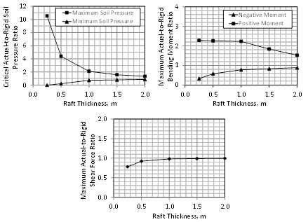
The findings indicate that raft thickness has significant effect on the critical maximum soil pressure and moderate effect on the critical minimum soil pressure. As expected, an increase in the thickness of the foundation makes the raft more rigid; resulting in reduced deformations, which leads to approximately uniform bearing pressure over the area below. Note that the maximum soil pressure is occurs below the corner columns due to the discontinuity of the raft at that location, which results in more deflection under these columns. The minimum soil pressure was observed at the centre of the interior panel since the 12 columns along the raft perimeter experience much more vertical deflection compared to the interior columns, leading to upward bulging between the four central interior columns. Also, the raft thickness has great effect on the bending moment, particularly the positive one that causes compression on the top of the raft. Note that negative moment occurs between the columns, whereas positive moment in regions located near the columns. In general, an increase in the raft thickness causes the positive moment to decrease and the negative moment to increase. For relatively thin rafts (< 1 m), the positive bending moment is less sensitive to the change in thickness than the negative moment. The opposite is true for relatively thick rafts (> 1 m). As the thickness increases, the raft becomes more rigid, causing it to curve less and leading to near-uniform soil bearing pressure within the whole raft panel. Within a panel, the negative moment and positive moment regions are somewhat equal to each other for thin rafts. For thick rafts, the contour line of contra-flexure is closer to the columns. The variation in bending moment with changes in raft thickness is mainly due to the change in soil bearing pressure distribution. In the case of thin rafts, the soil pressure under the columns is very large, whereas in the case of thick rafts the pressure is nearly uniform when subjected to the same loading. The findings can be explained by pointing out that large soil pressure under the columns (with small soil pressure near midspan) has little effect on the negative moment in regions midway between the columns. Alternatively, small soil pressure under the columns (with large soil pressure near midspan) has significant effect on the negative moment in regions midway between the columns. The effect of the raft thickness on shear in the raft is minimal, particularly for large raft thicknesses, because both the raft and the loading are symmetrical. Thus, the critical shear at the face of the columns is affected by the volume under the soil pressure under the raft, which is independent of the distribution of the soil pressure since the total loading is unchanged.
6.2. Effect of Modulus of Subgrade Reaction
The modulus of subgrade reaction, ks, represents the relationship between soil contact pressure and raft settlement over a unit area of soil. The reference raft considered is now analysed with different moduli of subgrade reaction, ranging from 25 to 400 MN/m3, while keeping all other parameters constant. Note that the lower values of ks represent soil composed of soft clay or loose sand, while the high values signify soil composed of well-graded, sand-gravel mixture. The impact of the modulus of subgrade reaction of the soil on the raft behaviour is presented in Fig. 7, in which the results are normalized with respect to those obtained from the analysis of an infinitely rigid raft.
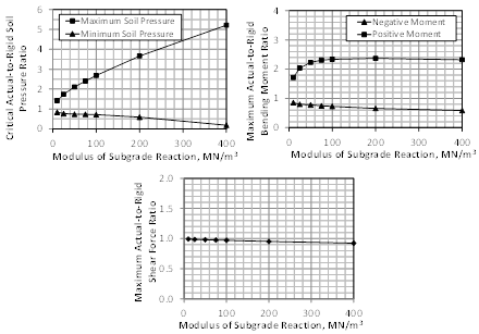
Findings of the analysis indicate that as ks increases, the maximum soil pressure occurring under the columns greatly increases. This is accompanied by a small decrease in the minimum pressure, which takes place in the central region of the panels. The reason for the change in critical soil pressure with the increase in ks is due to the stiffness of the soil under the raft. For rafts supported on stiff soil, there is concentration of high soil pressure directly under the columns, while for rafts on soft soil the pressure is more evenly distributed under the raft. This means that for the case of high ks, the raft under the columns deflect more than for the case of low ks. However, regions of the raft located at the centre of the panels (which represent minimum soil pressure) experience the same minimum soil bearing pressure, irrespective of ks. In all cases, the integration of the soil pressure over the underside area of the raft, which denotes the total applied load through the columns, is the same. The results also indicate that ks has slightly more effect on the positive moment under the columns than on the negative away from the columns, which can be attributed to the change in the soil bearing pressure distribution due to soil stiffness. While the minimum soil pressure remains the same in both cases, the maximum soil pressure is a little lower when ks is small compared to when ks is large, although the length over which the maximum pressure is applied is different in the two cases. Since the soil pressure between the columns, which is independent of ks, is responsible for the negative moment, the change in ks does not significantly affect that moment. The increase in the positive moment with increase in ks is due to the increase in the soil pressure in that region. Furthermore, the results show that this effect on the maximum shear within the raft is negligibility small because the critical shear in symmetrical rafts is a function of the total applied load on the raft, which is the same and is independent of the distribution of the soil pressure underneath.
6.3. Effect of Modulus of Elasticity of Concrete
The effect of the modulus of elasticity of the concrete, Ec, on the critical soil bearing pressure, bending moments, and shear is presented in Fig. 8, with the results being normalized with respect to those obtained from the analysis of an infinitely rigid raft. Most structural design codes provide equations for the modulus of elasticity in terms of the concrete compressive strength and mass density [21]. The reference raft is analysed with different moduli of elasticity, ranging from 20 to 50 GPa, while keeping all other parameters unchanged.
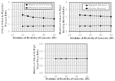
While the results indicate negligible change in the minimum soil bearing pressure with a change in the concrete modulus of elasticity, there is some effect on the maximum soil pressure, especially for concrete having low moduli of elasticity. As the modulus of elasticity increases, the maximum soil pressure under the column decreases due to the increased rigidity of the raft, which eventually results in a near uniform distribution of the soil pressure below it. The corresponding results for the internal bending moment and shear within the raft indicate minimal effect of the concrete modulus of elasticity on the positive bending moment and almost no effect on the negative bending moment and shear.
6.4. Effect of Spacing between Columns
The effect of the centre-to-centre spacing between columns of a raft on the critical soil pressure, bending moment, and shear is shown in Fig. 9, with the results being normalized with respect to an infinitely rigid raft. The analysis considers column spacing ranging between 3 and 10 m.
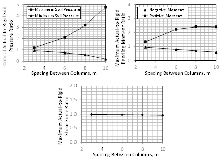
The analysis showed that the raft response greatly varies with the span length, even when the results are examined in a normalized format with respect to an infinitely rigid raft. This is because the distance between the supported columns significantly changes the behaviour of the raft from rigid to flexible as the span increases. For a raft consisting of small panels, the close spacing of the columns stiffens the raft and makes it hard to deform, causing the soil bearing pressure to be more evenly distributed underneath it. The opposite happens for a raft comprising of large panels; in that case, the soil pressure becomes concentrated within regions located in the vicinity of the columns. As expected, the results indicate that as the spacing between columns becomes longer, a sharp increase in the maximum pressure and moderate decrease in the minimum pressure take place, compared to their corresponding rigid rafts. Likewise, the spacing between columns has high impact on the critical negative moment and moderate effect on positive moment, although its effect on the positive moment becomes stagnant for very large column spacing. The results also reveal that the maximum shear in a flexible raft is very identical to its rigid counterpart irrespective of the spacing between columns.
7. Development of a Relative Rigidity Factor
For spread footings or rafts supporting rigid structures, ACI Committee 336 [22] recommends the use of a relative stiffness factor, Kr, developed in by Meyerhof [23], to differentiate between flexible and stiff shallow foundations:

where Ec is the modulus of elasticity of the concrete, B is the width of the foundation, Ib is the moment of inertia of the structure per unit length at right angles to B (i.e. t3/12), and Es is the modulus of elasticity of the soil that is supporting the structure, given by [1]:

where ks and ms are the modulus of subgrade reaction and Poisson’s ratio of the soil, respectively.
It is obvious from the previous two expressions that the measure of rigidity of a shallow foundation is proportional to Ec and t3, and inversely proportional to ks, B4 and (1-ms). For a square/rectangular spread footing or symmetrical raft that is composed of rectangular panels of length L and width B with column cross-section dimensions along the length equal to l and along the width equal to b, a dimensionless rigidity factor of the foundation, K’r, can be derived. This is accomplished by substituting the expressions of Es and Ib in that of Kr, filtering out the column dimension from the footing dimensions or panel dimensions of the raft, and eliminating the constants:

To check the validity of the above expression in quantifying flexural rigidity of a shallow foundation, the two case studies shown in Fig. 3 are analysed again using the finite element method by considering a wide range of parameters. Each time, the spread footing and raft foundation are analysed twice, once as flexible with the actual values of the parameters and another time as infinitely rigid by drastically increasing the raft thickness. The parameters that are considered in the study are: (1) thickness of the foundation, (2) number of bays along the length and width, (3) concrete modulus of elasticity, (4) soil subgrade reaction, (5) column spacing along the length and width, (6) cross-section dimensions of the columns, and (7) aspect ratio of the panels within the foundation. In total, 70 different rafts and 46 different spread footings (34 square and 13 rectangular) are considered. Figure 10 shows the relationship between the relative rigidity factor and critical soil pressure, bending moment and shear force for symmetrical rafts, normalized with respect to those of an infinitely rigid foundation. The corresponding results for spread footings are presented in Fig. 11.
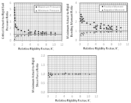
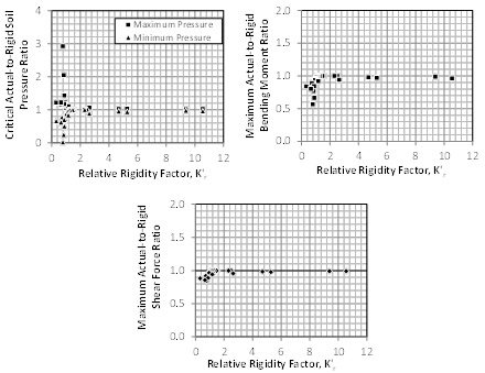
The outcome indicates excellent correlation between the developed rigidity factor and maximum load effect. The results confirm that the relative rigidity of the foundation greatly impact the critical soil bearing pressure and bending moment, but has negligible influence on the shear force. Furthermore, a relative rigidity factor K’r=1 can be considered as the threshold above which a raft foundation can approximately be considered rigid.
7. Conclusion
Findings of the study on shallow foundation lead to the following conclusions:
- The stiffness of a foundation relative to the soil underneath it greatly affects the magnitude and distribution of soil bearing pressure, which in turn influences the critical internal forces within the foundation.
- The relative stiffness of a spread footing or raft foundation is greatly affected by the dimensions of the foundation, and to a lesser extent the modulus of subgrade reaction of the soil and modulus of elasticity of the concrete.
- As the raft’s relative stiffness increases, the soil bearing pressure approaches a near uniform distribution state, which causes a reduction in the maximum positive moment and amplification in the maximum negative moment. For the case of spread footings, an increase in the relative stiffness results in a decrease in the maximum bending moment at the face of the column.
- The effect of the relative stiffness on shear in shallow foundations is negligibly small since the critical internal shear within the foundation is a function of the applied load and is independent of the soil pressure distribution under the foundation.
- Based on the early work of Meyerhoff, a quantitative measure for the relative foundation rigidity with respect to the soil was developed for the sake of checking whether or not a given shallow foundation can be reasonably analysed using the traditional rigid foundation approach.
Acknowledgements
Special thanks are due to Engineer Abdul Raouf Al-Shawwa, Engineer Pouya Partazian, and Professor Aqeel Ahmed for carrying out the finite element analyses. The authors would also like to acknowledge the financial support through grant FRG11-II-22, provided by the Office of Research at the American University of Sharjah, UAE, through the university’s faculty research grant program.
References
[1] J.E. Bowles, "Foundation Analysis and Design," 5th Edition, McGraw-Hill, 2001, 1175 p.
[2] B.M. Das and N. Sivakugan, "Principles of Foundation Engineering," 9th Edition, Cengage Learning, 2018, 944 p.
[3] R. Jarquio, "Steel reinforcement for rectangular footing with biaxial bending," Proc., Int. Conf. on Application of Codes, Design and Regulations, Institute of Civil Engineers, London, 2005, pp. 609-616.
[4] H.M. Algin, "Practical formula for dimensioning a rectangular footing." Eng. Structures, 29(6), 2007, pp. 1128-1134.
View Article
[5] G.T. Houlsby and M.J. Cassidy, "A plasticity model for the behaviour of footing on sand under combined loading." Geotechnique, 53(2), 2002, pp. 117-129.
View Article
[6] S. Gourvenec, M.F. Randolph, and O. Kingsnorth, "Undrained bearing capacity of square and rectangular footings." Int. J. Geomech., 6(3), 2006, pp. 147-157.
View Article
[[7] J. Kumar and P. Ghosh, "Ultimate bearing capacity of two interfering rough strip footings." Int. J. Geomech., 7(1), 2007, pp. 53-63.
View Article
[8] N. Yamamoto, M.F. Randolph, and I. Einav, "Simple formulas for the response of shallow foundations on compressible sands." Int. J. Geomech., 8(4), 2008, pp. 230-239.
View Article
[9] S. Gourvenec, M.F. Randolph, and O. Kingsnorth, "Undrained bearing capacity of square and rectangular footings." Int. J. Geomech., 6(3), 2006, pp. 147-157.
View Article
[10] J.A. Rodriguez-Gutierrez and J.D. Aristizabal-Ochoa, "Rigid Spread Footings Resting on Soil Subjected to Axial Load and Biaxial Bending. I: Simplified Analytical Method", International Journal of Geomechanics, Vol 13, Issue 2, 2013, pp. 109-119.
View Article
[11] S. Teli, P. Kundhani, V. Choksi, P. Sinha and K.R. Iyer "Analytical Study on the Influence of Rigidity of Foundation and Modulus of Subgrade Reaction on Behaviour of Raft Foundation" Lecture Notes in Civil Engineering, Springer, V. 56, Advances in Computer Methods and Geomechanics, 2020, pp 181-194.
View Article
[12] J.F. Gong, X.L. Huang and J. Teng "Rigidity characteristic and deformation calculation of large-area thick raft foundation" Proceedings of the 16th International Conference on Soil Mechanics and Geotechnical Engineering, Millpress Science Publishers/IOS Press, 2005, pp. 1471-1475.
[13] M.A. Alshorafa "Modifications of Conventional Rigid and Flexible Methods for Mat Foundation Design" MS Thesis, Islamic University of Gaza, Civil Engineering Department, 2008, 142 p.
[14] Z. Çekinmez, "Effect of Foundation Rigidity On Contact Stress Distribution In Soils With Variable Strength / Deformation Properties", Thesis Submitted to the Graduate School of Natural and Applied Sciences of Middle East Technical University, January 2010, 100 p.
[15] T.V. Pillay "Soil-Structure Interaction and Structural Design of Raft-Foundation and Reinforced Concrete Superstructure" Practice Periodical on Structural Design and Construction, ASCE, Vol. 26, Issue 3, August, 2021.
View Article
[16] S.W. Tabsh, and A-R Al-Shawa, "Effect of Spread Footing Flexibility on Structural Response," Practice Periodical on Structural Design and Construction, ASCE, Volume 10, Issue 2, April 2005, pp. 109-114.
View Article
[17] S.W. Tabsh, M. El-Emam, and P. Partazian, "Numerically Based Parametric Analysis of Mat Foundations," Practice Periodical on Structural Design and Construction, ASCE, V. 25, No.2, May 2020. Paper # 04020009.
View Article
[18] S.W. Tabsh and M. El-Emam, "Influence of Foundation Rigidity on the Structural Response of Mat Foundation," Advances in Civil Engineering, Hindawi, Volume 2021, October 2021, Article ID# 5586787.
View Article
[19] CSI, "Reference manual for SAP2000, ETABS, SAFE and CSiBridge," Computers and Structures, Inc., Berkeley, CA, 2016, 534 pages.
[20] SAFE, "Design of Slabs, Beams and Foundations - Reinforced and Post-Tensioned Concrete," Verification Manual, Computers and Structures, Inc. (CSI), Berkeley, CA, 2016, 505 pages
[21] ACI 318, "Building Code Requirements for Structural Concrete and Commentary", ACI Committee 318, American Concrete Institute, Farmington Hills, MI, 2019, pp. 623.
[22] ACI 336, "Suggested Design Procedures for Combined Footings and Mats," Journal of the American Concrete Institute, Vol. 63, No. 10, 1988, pp. 1041-1077.
[23] G.G. Meyerhof, "Some Recent Foundation Research and Its Application to Design," The Structural Engineer, Vol. 31, No. 6, London, 1953, pp. 151-167.
[1] J.E. Bowles, "Foundation Analysis and Design," 5th Edition, McGraw-Hill, 2001, 1175 p.
[2] B.M. Das and N. Sivakugan, "Principles of Foundation Engineering," 9th Edition, Cengage Learning, 2018, 944 p.
[3] R. Jarquio, "Steel reinforcement for rectangular footing with biaxial bending," Proc., Int. Conf. on Application of Codes, Design and Regulations, Institute of Civil Engineers, London, 2005, pp. 609-616.
[4] H.M. Algin, "Practical formula for dimensioning a rectangular footing." Eng. Structures, 29(6), 2007, pp. 1128-1134. View Article
[5] G.T. Houlsby and M.J. Cassidy, "A plasticity model for the behaviour of footing on sand under combined loading." Geotechnique, 53(2), 2002, pp. 117-129. View Article
[6] S. Gourvenec, M.F. Randolph, and O. Kingsnorth, "Undrained bearing capacity of square and rectangular footings." Int. J. Geomech., 6(3), 2006, pp. 147-157. View Article
[[7] J. Kumar and P. Ghosh, "Ultimate bearing capacity of two interfering rough strip footings." Int. J. Geomech., 7(1), 2007, pp. 53-63. View Article
[8] N. Yamamoto, M.F. Randolph, and I. Einav, "Simple formulas for the response of shallow foundations on compressible sands." Int. J. Geomech., 8(4), 2008, pp. 230-239. View Article
[9] S. Gourvenec, M.F. Randolph, and O. Kingsnorth, "Undrained bearing capacity of square and rectangular footings." Int. J. Geomech., 6(3), 2006, pp. 147-157. View Article
[10] J.A. Rodriguez-Gutierrez and J.D. Aristizabal-Ochoa, "Rigid Spread Footings Resting on Soil Subjected to Axial Load and Biaxial Bending. I: Simplified Analytical Method", International Journal of Geomechanics, Vol 13, Issue 2, 2013, pp. 109-119. View Article
[11] S. Teli, P. Kundhani, V. Choksi, P. Sinha and K.R. Iyer "Analytical Study on the Influence of Rigidity of Foundation and Modulus of Subgrade Reaction on Behaviour of Raft Foundation" Lecture Notes in Civil Engineering, Springer, V. 56, Advances in Computer Methods and Geomechanics, 2020, pp 181-194. View Article
[12] J.F. Gong, X.L. Huang and J. Teng "Rigidity characteristic and deformation calculation of large-area thick raft foundation" Proceedings of the 16th International Conference on Soil Mechanics and Geotechnical Engineering, Millpress Science Publishers/IOS Press, 2005, pp. 1471-1475.
[13] M.A. Alshorafa "Modifications of Conventional Rigid and Flexible Methods for Mat Foundation Design" MS Thesis, Islamic University of Gaza, Civil Engineering Department, 2008, 142 p.
[14] Z. Çekinmez, "Effect of Foundation Rigidity On Contact Stress Distribution In Soils With Variable Strength / Deformation Properties", Thesis Submitted to the Graduate School of Natural and Applied Sciences of Middle East Technical University, January 2010, 100 p.
[15] T.V. Pillay "Soil-Structure Interaction and Structural Design of Raft-Foundation and Reinforced Concrete Superstructure" Practice Periodical on Structural Design and Construction, ASCE, Vol. 26, Issue 3, August, 2021. View Article
[16] S.W. Tabsh, and A-R Al-Shawa, "Effect of Spread Footing Flexibility on Structural Response," Practice Periodical on Structural Design and Construction, ASCE, Volume 10, Issue 2, April 2005, pp. 109-114. View Article
[17] S.W. Tabsh, M. El-Emam, and P. Partazian, "Numerically Based Parametric Analysis of Mat Foundations," Practice Periodical on Structural Design and Construction, ASCE, V. 25, No.2, May 2020. Paper # 04020009. View Article
[18] S.W. Tabsh and M. El-Emam, "Influence of Foundation Rigidity on the Structural Response of Mat Foundation," Advances in Civil Engineering, Hindawi, Volume 2021, October 2021, Article ID# 5586787. View Article
[19] CSI, "Reference manual for SAP2000, ETABS, SAFE and CSiBridge," Computers and Structures, Inc., Berkeley, CA, 2016, 534 pages.
[20] SAFE, "Design of Slabs, Beams and Foundations - Reinforced and Post-Tensioned Concrete," Verification Manual, Computers and Structures, Inc. (CSI), Berkeley, CA, 2016, 505 pages
[21] ACI 318, "Building Code Requirements for Structural Concrete and Commentary", ACI Committee 318, American Concrete Institute, Farmington Hills, MI, 2019, pp. 623.
[22] ACI 336, "Suggested Design Procedures for Combined Footings and Mats," Journal of the American Concrete Institute, Vol. 63, No. 10, 1988, pp. 1041-1077.
[23] G.G. Meyerhof, "Some Recent Foundation Research and Its Application to Design," The Structural Engineer, Vol. 31, No. 6, London, 1953, pp. 151-167.