International Journal of Civil Infrastructure (IJCI)
ISSN: 2563-8084

Volume 6 - Year 2023- Pages 36-40
DOI: 10.11159/ijci.2023.005
A Finite Element Approach to Investigate the Deformation Behaviour in Deep Excavation for TBM Launching Shaft
Sultan Al Shafian1, Md. Nafis Imtiyaz2, Mostafiz Emtiaz3,
1Islamic University of Technology, Department of Civil Engineering
Boardbazar, Gazipur-1704, Bangladesh
sultanalshafian@iut-dhaka.edu
2Arcadis US Inc.
10205 Westheimer Road,#800,Houston,Texas 7704,USA
nafisimtiyaz.cee@gmail.com
3RRP Consulting Engineers, LLC
1400 Broadfield Blvd, Suite 400, Houston, Texas 77084
mostafizemtiaz0805@gmail.com
Abstract - Being one of the densely populated cities in the world, Dhaka is going through massive changes for infrastructure construction. Various mega projects like underground metro have been undertaken by the government in recent years. This kinds of mega projects certainly need huge excavation works for underground stations, ventilation shaft, launching box and for many other reasons. A careful assessment of the excavation work is required to reduce the risk of failure during construction. Finite element analysis (FEM) can support as an excellent tool to understand the soil behaviour during excavation. As Dhaka has a layer of soft soil in the upper strata, the risks are also higher for these kinds of deep excavation works. This paper analyze a specific section in Dhaka city where future metro rail constructions can take place. An idealized section of a tunnel boring machine(TBM) launching shaft is considered for the excavation analysis where the concrete diaphragm wall has been considered as earth retaining system. Along with deformation, the forces have also been studied to understand the impact due to construction.
Keywords: Deep Excavation, FEM, Plaxis 2D, Constitutive Model, Launching Shaft.
© Copyright 2023 Authors - This is an Open Access article published under the Creative Commons Attribution License terms. Unrestricted use, distribution, and reproduction in any medium are permitted, provided the original work is properly cited.
Date Received: 2023-05-24
Date Revised: 2023-07-06
Date Accepted: 2023-07-15
Date Published: 2023-08-03
1. Introduction
Ensuring safety during mega construction activities like deep excavation is a responsibility of employer, contractor, engineers and all the stakeholders. Inadequate site investigations, poor workmanship, ignoring backfill loads, construction practices that create excessive earth pressures, poorly planned support systems and inadequate allowances for deflections etc can cause failure during deep excavation works.[1]-[2]
So, it is important to understand the deformation behaviour of the soil during excavation specially the soft soil like Bangladesh. Recently, the government of Bangladesh has undertaken a metro rail project in Dhaka with a total length of 128.741 kilometres where out of this total length, 67.569 kilometres will be elevated, while 61.172 kilometres will be underground [3]. These kinds of challenging developments require massive excavations in most of the times in close proximity to pre-existing buildings and underground utilities. The risks associated with subsurface structures can be greatly reduced if the soil behaviours, especially for the soft soils of Dhaka [4], are thoroughly studied prior to excavation.
The finite element analysis (FEM) is a useful tool that may be utilised for the investigation of deep excavation. FEM analysis can capture the soil-structure interaction at different stages of the construction more precisely which allows the engineers to design the supporting systems of deep excavation more precisely. In this research, an idealized launching shaft excavation has been considered. Studying the effect of excavation for this section will provide an insightful knowledge for any deep excavation works especially for tunnelling projects in Bangladesh. The section has been analysed for different crucial scenarios by changing the excavation depth and embedment depth of D-wall.
2. Literature Review
For deep excavation, diaphragm wall is an excellent choice for providing support during the excavation works. Also, the range of application of diaphragm wall is huge [5]. The lateral displacement occurs on the support system due to the removal of soil has been studied by researchers for a long time. Peck [6] developed empirical method to predict lateral wall movement based on real case scenarios. Later, Clough and O’Rourke[7] have developed a semi-empirical method for estimating excavation deformation in soft clays whereby the maximum lateral deformations induced by excavation.
With the development of computer technology, solving complex civil engineering problem has become easier. However, Finite Element Method (FEM) has become popular among engineers for solving deep excavation problems as it is less time consuming and lots of iterations can be run. Engineers have been trying to simulate the excavation process using FEM for a long time [8]. Various case studies have been done using FEM method and compared with real life displacement values.[9]
To simulate the excavation and soil behaviour a proper constitutive model has to be chosen [10]-[13]. Mohr-coulomb(MC) model is one of the popular soil constitutive model which has been used for similar excavation analysis for it’s simplicity [14]. This model require very few parameters and it can give some quick idea about the soil behaviour. On the other hand, Hardening soil (HS) model has also been specially for excavation analysis as it can the essential engineering behaviour such as ground settlement, wall deflection, bending moment and earth pressure distribution satisfactorily [15]. In this research, a comparative study has been done using both Mohr-coulomb and Hardening soil model using the Plaxis 2D finite element program.
3. Excavation Geometry
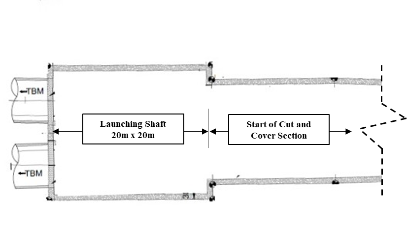
Figure 1 shows the idealized section which has been considered for the analysis.
 (a)
(a)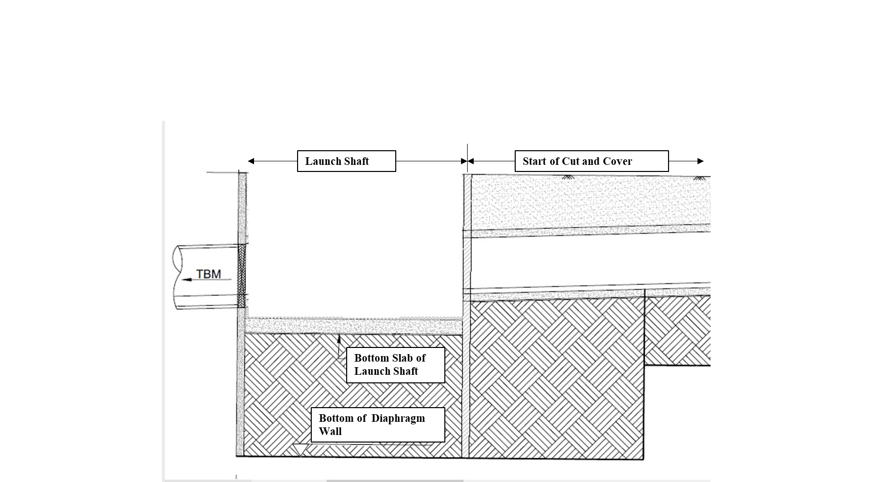 (b)
(b)The idealised section is a 20m x 20 m square TBM (Tunnel Boring Machine) launching shaft which is 17.0m deep. The launching shaft is connected with 50.0m long cut and cover section. Bottom-up construction approach has been considered for executing this deep excavation work.
4. FEM Analysis
A 2D plane strain model has been developed due to the uniform cross section of the problem. Because of their superiority at solving complex issues, 15-noded triangular elements were chosen.
4. 1. Material Properties of the Model
In this analysis, Mohr-coulomb and Hardening Soil model has been adopted as constitutive model. The Mohr-coulomb requires mainly Young’s modulus (E) ,Poisson’s ratio (ν) ,Cohesion(c) , Friction angle (φ) and Dilatancy angle (ψ) to model the soil behaviour. On the other hand, the hardening soil model also requires secant stiffness E50ref, tangent stiffness for primary load Eoedref and a stiffness modulus at unloading/reloading stiffness Eurref.Soil parameters used in the ground model has been shown in Table 1.
Table 1. Soil Properties
|
Parameter |
Soil 1 |
Soil 2 |
Soil 3 |
Soil 4 |
Soil 5 |
|
Soil Type |
Fill |
Soft clay |
Medium Dense Sand |
Stiff Clay |
Dense Sand |
|
Depth, m |
0-6 |
6-12 |
12-20 |
20-38 |
38-60 |
|
Unit Weight (Unsaturated), kN/m3 |
19.7 |
18.7 |
20 |
19.3 |
20.5 |
|
Unit Weight (saturated), kN/m3 |
20 |
19 |
20.5 |
19.5 |
21 |
|
E ≅ E50 ,(mPa) |
5 |
12 |
60 |
110 |
150 |
|
Eoedref (mPa) |
5 |
12 |
60 |
110 |
150 |
|
Eurref =3 E50ref (mPa) |
15 |
36 |
180 |
330 |
450 |
|
Cohesion, kN/m2 |
0 |
7 |
0 |
15 |
0 |
|
Friction angle, φ |
25 |
25 |
30 |
25 |
34 |
The soil profile has been considered based on the ongoing feasibility study reports of various mega projects in Dhaka city [16] .However, due to unavailability of some properties, empirical correlations have been used.
For simulating the diaphragm wall(D-wall) and the concrete base slab, plate material has been used. Table 2 shows the properties of plate materials used in the model:
Table 2. Plate Material Properties
|
Parameter |
Diaphragm Wall |
Concrete Base Slab |
|
Unit Weight (kN/m/m) |
20 |
37.5 |
|
EA (kN/m) |
28E06 |
52.5E06 |
|
EI (kN m2/m) |
1.5E06 |
9.84E06 |
|
ν |
0.2 |
0.2 |
To model the struts, node-to-node anchor has been used. Table 3 shows the properties of struts used in different levels of excavation.
Table 3. Anchor Material Properties
|
Parameter |
Strut 1 |
Strut 2 |
Strut 3 |
Strut 4 |
|
EA (kN/m) |
2.8E06 |
6.7E06 |
6.7E06 |
14.1E06 |
|
Lspacing (m) |
6 |
6 |
6 |
6 |
4. 2. Model Description and Construction Sequence
In geotechnical engineering, soil behaviour depends on loading histories and stress pathways. To accurately forecast soil behaviour and structural response, the construction stages must be simulated properly in numerical analysis. In Plaxis 2D, it is possible to define the construction stages and analyze the soil behaviour during different construction stages. Following construction stages have been followed during the analysis:
- Initial Phase: Generation of the initial stress state-K0 procedure
- Step 1: Activating the Plate materials (diaphragm wall)
- Step 2: First layer (up to 3.0m) of soil excavation (by deactivating the soil cluster)
- Step 3: Second layer (up to 6.6m) of soil excavation and activation of the first strut to simulate the supporting system.
- Step 4: Third layer (up to 8.7m) of soil excavation and activation of the second strut to simulate the supporting system.
- Step 5: Fourth layer (up to 13.9m) of soil excavation and activation of the third strut to simulate the supporting system.
- Step 6: Final layer (up to 17.0m) of soil excavation and activation of the fourth strut to simulate the supporting system.
- Step 7: Activation of the bottom slab
In Figure 2, the material model has been shown for better understanding.
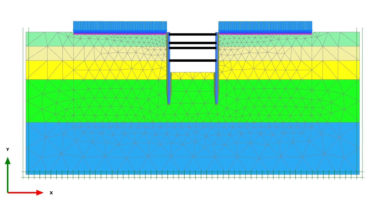
The water level has been considered at 5.0m below from the existing ground level.
5. Results
Both models were analysed in drained condition using two different constitutive model. The deformation and forces at the final stages of the excavation of the diaphragm wall is plotted in graph for comparison. Two separate cases have been considered for better understanding of the deformation behaviour. In first case, different embedment depth of the wall is taken for analysis .In second case, the excavation depth has been changed.
5. 1. Case 1- Embedment Depth of D-Wall
The embedment depth of d-wall plays a crucial part for the stability during the excavation works. In this analysis, three different embedment depths have been considered ,25m, 30 m and 35m. After displacement obtained from both MC and HS model analysis, a comparison graph has been plotted for better understanding in figure 3.
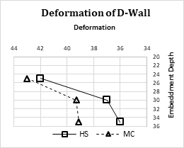
As it can be seen that, the maximum displacement is observed in MC model . The Hardening soil has shown less displacement than the MC model. However ,for both model, with increment of embedment depth of the D-wall, the displacement value decreased.
The Variation of forces for these three different embedment depths has been shown in the table 4
Table 4. Forces variation in D-wall for Different Embedment Depth.
|
D-Wall |
Bending Moment Kn/m/m |
Axial Force (kN/m)
|
Shear Force (kN/m) |
|||
|
MC |
HS |
MC |
HS |
MC |
HS |
|
|
25 |
1702 |
1764 |
554 |
503 |
725 |
717 |
|
30 |
1491 |
1554 |
787 |
758 |
609 |
660 |
|
35 |
1507 |
1569 |
858 |
871 |
605 |
632 |
5. 2. Case 2- Excavation Depth
Three different excavation depth has been considered to understand the relationship between excavation depth and displacement behaviour of D-Wall which has been plotted in figure 4
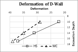
As the excavation depth increases, the deformation of the diaphragm wall increases as well. Similar increment is observed for both soil models. The variation of forces has been tabulated in Table 5
Table 5. Error rates for four different trials.
|
Excavation Depth m |
Bending Moment kN/m/m |
Axial Force (kN/m)
|
Shear Force (kN/m) |
|||
|
MC |
HS |
MC |
HS |
MC |
HS |
|
|
10 |
781 |
723 |
383 |
366 |
282 |
313 |
|
14 |
1307 |
1368 |
698 |
708 |
541 |
631 |
|
17 |
1491 |
1554 |
787 |
758 |
609 |
660 |
5. Limitations and Future Directions
The limitations of this investigation should be considered when interpreting the results. First, the adoption of constitutive models, such as the Mohr-Coulomb and Hardening Soil models, entails assumptions and simplifications that may not adequately represent the complexities of soil behaviour. Secondly, the precision of the results is highly dependent on the exact determination of input parameters and the use of empirical correlations and assumptions for properties introduces additional uncertainty. Thirdly, considering the uniform cross section of the problem in 2D Plane strain may restrict the representation of spatial variations of the site soil strata. Furthermore, simulations of boundary conditions and construction sequences may differ from actual field conditions, thereby introducing additional uncertainty. It is important to recognize these limitations to ensure a cautious interpretation of the research’s findings and to identify areas for additional research for future. For future study, flow-deformation coupled analysis on the movement of D-wall can be done. Also, partial drainage impact during the construction of D-wall into shaft can also be studied for such type of deep excavation.
6. Conclusion
This paper aims to provide a basic understanding of the deformation behaviour of the diaphragm wall for multi-layered soft soil conditions of Dhaka city. In order to accomplish this, a parametric analysis has been carried out, during which several construction scenarios, such as varying embedment depths of the d-wall and different excavation depths, have been taken into consideration.
From the analysis it has been observed that, the deformation of the d-wall decreases for greater embedment depth and increases with the increment of excavation depth. For both cases, the Mohr-coulomb soil model shows higher displacement and forces than the Hardening soil model. As Hardening soil model considers loading and unloading behaviour, it gives conservative values. Also, the presence of clay layers with higher cohesion values can also impact the deformation behaviour of the structure.
As some of the soil parameters were assumed for the analysis, it is advisable to use laboratory test results for better outcome.
References
[1] M. Puller, "Deep Excavations: A Practical Manual," Thomas Telford Publishing: London, UK, 1996.
[2] G. B. Sowers and G. G. Sowers, "Failures of bulkhead and excavation bracing," Civil Eng ASCE 37(1), 1983 pp. 72-77.
[3] DMTCL.(2022,December 31).Progress of Projects under DMTCL- December 2022 [Online].Available: .
View Article
[4] Arifuzzaman and A. Hasan, "Evaluation of Foundation Difficulties over Soft Organic Soil," Jordan Journal of Civil Engineering, 2013, vol. Volume 7, no. 4, pp. 440-449.
[5] M. E. A. El-Razek, "New method for construction of diaphragm walls," Journal of construction engineering and management, 1999, 125(4), pp.233-241.
View Article
[6] R.B. Peck, "Deep Excavation and Tunneling in Soft Ground. State-of-the-Art Report." Proceedings of the 7th International Conference on Soil Mechanics and Foundation Engineering, Mexico, 1969, 225-290.
[7] G.W. Clough, T.D. O'Rourke, " Construction Induces Movements of Insitu Walls", Proceedings of Design and Performance of Earth Retaining Structures, ASCE, Cornell University, Ithaca,NY, June 18-21,1990, pp. 439-469.
[8] I. A. Mana, "Finite element analyses of deep excavation behavior in soft clay," PhD thesis, Stanford University, 1978.
[9] Aktas, T., Calisan, O. and Cokca, E. (2018) 'Finite element analysis of deep excavation: A case study', Springer Series in Geomechanics and Geoengineering, pp. 885-888. doi:10.1007/978-3-319-97115-5_1.
View Article
[10] D. Kolymbas, "The misery of constitutive modelling," Constitutive Modelling of Granular Materials, Springer, Berlin, 2000, pp. 11-24.
View Article
[11] D. M. Wood, "The role of models in civil engineering," Constitutive modelling of granular materials, Springer, Berlin, 2000, pp. 37-55.
View Article
[12] H. F. Schweiger, "The role of advanced constitutive models in geotechnical engineering," Geomechanik und Tunnelbau: Geomechanik und Tunnelbau, 2008, 1(5), pp. 336-344.
View Article
[13] M. U. Kabir, M. S. Islam, F. B. Nazrul and H. M. Shahin, "Comparative Stability and Behabiour Assessment of a Hill Slope on Clayey Sand Hill Tracts," International Journal of Engineering Trends and Technology (IJETT), Published by Seventh Sense Research Group, 2023 71(1), pp. 11‑24.
View Article
[14] D. D. Zhang, J. F. Zhou, W. G. Zhang, C. B. Zhu, R. R. Sun, L. J. Ji and Z. X. Wu, "The finite element analysis of the excavation on adjacent buildings based on mohr coulomb model," In Advanced Materials Research, Trans Tech Publications Ltd. 2012, Vol. 374, pp. 2171-2175.
View Article
[15] A. Usmani, G. V. Ramana and K. G. Sharma, "Analysis of braced excavation using hardening soil model," Indian Geotechnical Conference- Geotrendz, IGS Mumbai chapter & IIT Bombay, 2010, pp. 231-234.
[16] Japan International Cooperation Agency (JICA) (2018) The Preparatory Study on The Dhaka Mass Rapid Transit Development Project (Line 1) In Bangladesh Draft Final Report 2. Dhaka, Bangladesh: JICA
[1] M. Puller, "Deep Excavations: A Practical Manual," Thomas Telford Publishing: London, UK, 1996.
[2] G. B. Sowers and G. G. Sowers, "Failures of bulkhead and excavation bracing," Civil Eng ASCE 37(1), 1983 pp. 72-77.
[3] DMTCL.(2022,December 31).Progress of Projects under DMTCL- December 2022 [Online].Available: . View Article
[4] Arifuzzaman and A. Hasan, "Evaluation of Foundation Difficulties over Soft Organic Soil," Jordan Journal of Civil Engineering, 2013, vol. Volume 7, no. 4, pp. 440-449.
[5] M. E. A. El-Razek, "New method for construction of diaphragm walls," Journal of construction engineering and management, 1999, 125(4), pp.233-241. View Article
[6] R.B. Peck, "Deep Excavation and Tunneling in Soft Ground. State-of-the-Art Report." Proceedings of the 7th International Conference on Soil Mechanics and Foundation Engineering, Mexico, 1969, 225-290.
[7] G.W. Clough, T.D. O'Rourke, " Construction Induces Movements of Insitu Walls", Proceedings of Design and Performance of Earth Retaining Structures, ASCE, Cornell University, Ithaca,NY, June 18-21,1990, pp. 439-469.
[8] I. A. Mana, "Finite element analyses of deep excavation behavior in soft clay," PhD thesis, Stanford University, 1978.
[9] Aktas, T., Calisan, O. and Cokca, E. (2018) 'Finite element analysis of deep excavation: A case study', Springer Series in Geomechanics and Geoengineering, pp. 885-888. doi:10.1007/978-3-319-97115-5_1. View Article
[10] D. Kolymbas, "The misery of constitutive modelling," Constitutive Modelling of Granular Materials, Springer, Berlin, 2000, pp. 11-24. View Article
[11] D. M. Wood, "The role of models in civil engineering," Constitutive modelling of granular materials, Springer, Berlin, 2000, pp. 37-55. View Article
[12] H. F. Schweiger, "The role of advanced constitutive models in geotechnical engineering," Geomechanik und Tunnelbau: Geomechanik und Tunnelbau, 2008, 1(5), pp. 336-344. View Article
[13] M. U. Kabir, M. S. Islam, F. B. Nazrul and H. M. Shahin, "Comparative Stability and Behabiour Assessment of a Hill Slope on Clayey Sand Hill Tracts," International Journal of Engineering Trends and Technology (IJETT), Published by Seventh Sense Research Group, 2023 71(1), pp. 11‑24. View Article
[14] D. D. Zhang, J. F. Zhou, W. G. Zhang, C. B. Zhu, R. R. Sun, L. J. Ji and Z. X. Wu, "The finite element analysis of the excavation on adjacent buildings based on mohr coulomb model," In Advanced Materials Research, Trans Tech Publications Ltd. 2012, Vol. 374, pp. 2171-2175. View Article
[15] A. Usmani, G. V. Ramana and K. G. Sharma, "Analysis of braced excavation using hardening soil model," Indian Geotechnical Conference- Geotrendz, IGS Mumbai chapter & IIT Bombay, 2010, pp. 231-234.
[16] Japan International Cooperation Agency (JICA) (2018) The Preparatory Study on The Dhaka Mass Rapid Transit Development Project (Line 1) In Bangladesh Draft Final Report 2. Dhaka, Bangladesh: JICA