International Journal of Civil Infrastructure (IJCI)
ISSN: 2563-8084

Volume 6 - Year 2023- Pages 51-57
DOI: 10.11159/ijci.2023.007
Numerical Study of HSS-to-HSS Moment Connections Subjected to Out-of-Plane Loading: Effect of Connection Eccentricity
Janak Raj Joshi1,2, and Jianwei Huang1
1Southern Illinois University Edwardsville (SIUE), Department of Civil Engineering
Edwardsville, IL, USA 62026
jiahuan@siue.edu
Abstract - Hollow structural sections (HSS) have been used in various types of structures due to several desirable properties, such as a high strength-to-weight ratio, good compression, bending, and torsional resistance. Extensive research has been conducted to study the behaviors of HSS-to-HSS moment connections subjected to in-plane loading, however, studies on the behaviors under out-of-plane loading are limited. This paper aims to investigate the effects of connection eccentricity on the capacity of HSS-to-HSS moment connections subjected to out-of-plane loading by using finite element (FE) simulations. Two connection configurations were examined with different branch-to-chord width ratios (β); three cases of section corner radii were explored for each configuration. Based on von Mises yield criterion, the onset yield loads for connections were determined and compiled for comparisons. The results from this study showed that a linear downward trend is observed between the onset yield load at chord wall and the connection eccentricity, which suggests that the connection with eccentricity is more vulnerable to yielding at the chord wall as compared to a concentric connection. Also, with a higher width ratio (β), the connection was found to achieve a higher onset yield load. Furthermore, the connection with a larger section corner radius was observed to have a higher onset yield load.
Keywords: Hollow structural section (HSS), moment connection, eccentricity, corner radius, out-of-plane loading.
© Copyright 2023 Authors - This is an Open Access article published under the Creative Commons Attribution License terms. Unrestricted use, distribution, and reproduction in any medium are permitted, provided the original work is properly cited.
Date Received: 2023-05-29
Date Revised: 2023-07-10
Date Accepted: 2023-07-21
Date Published: 2023-08-29
1. Introduction
Rectangular and square hollow structural sections (HSS) have been used in various types of structures due to several desirable properties, such as a high strength-to-weight ratio, good compression, bending, and torsional resistance; also, the flat surfaces of HSS are architecturally pleasing and can provide ease of storage and stacking [1-5]. To date, HSS sections have been typically used as columns, bracing members, cladding supports, truss members, and moment resisting frames (beam and column members) [1-5]. In some situations, eccentric HSS-to-HSS connections are required, e.g., cantilevered canopies, framing connected to stairwells, and situations due to geometric or site limitations [6]. Recently, a study on the effect of connection eccentricity on HSS-to-HSS moment connections subjected to out-of-plane loading was reported, in which a preliminary analysis was performed first, followed by a refined analysis; the preliminary analysis was conducted to narrow down the parameters for the refined analysis [6]. Fig. 1 and Fig. 2 show the two-dimensional (2-D) and three-dimensional (3-D) views of the HSS-to-HSS moment connection, respectively, whereas Fig. 3 illustrates the connection eccentricity in an HSS-to-HSS moment connection [6]. Note that the preliminary analyses were performed on the finite element (FE) models with a chord length of 5 ft (1.52 m) and a branch length of 2 ft (0.61 m), while the refined analyses used a chord length of 30 in (0.762 m) and a branch length of 12 in (0.305 m) [6]. The results from the refined analyses showed that the chord wall yielding governs the design of eccentric connections; the load capacity (i.e., onset yield moment) decreases as the connection eccentricity increases for an HSS-to-HSS moment connection subjected to out-of-plane loading [6].
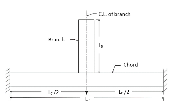
(Adapted from [6])
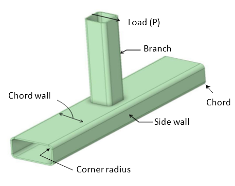
(Adapted from [6])
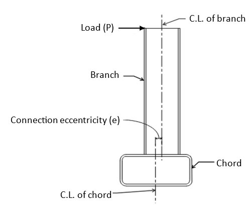
(Adapted from [6])
It is important to point out that the model used in the refined analyses in [6] only had a length of 30 in (0.762 m), which was deemed to be small and is not practical for real applications. Also, the research in [6] only examined the HSS sections with a corner radius of 3 times the thickness of the member [6]. Note that the corner radius (r) for square and rectangular structural HSS can range from a minimum of 1.6 times the thickness (t) of the member (r=1.6t) to a maximum of 3.0 times the thickness of the member (r=3t) when the member thickness is less than 0.4 in (10.16 mm) [7]. For a given HSS section, a larger corner radius reduces the flat portion of the chord wall (see Fig. 2), and it might affect the stress distribution developed along the chord wall when the branch is subjected to an out-of-pane loading. Therefore, this study intended to investigate the influence in the connection load capacity with change in corner radius.
To gain a better understanding of the effect of connection eccentricity, two connection configurations in the refined analysis in [6] were adopted in this paper for studies, as shown in Table 1 and Table 2. As can be seen, HSS 12x6x3/8 section was used as the chord member for both configurations, whereas HSS 6x6x5/16 section was used as the branch member in Configuration 1 (Config. 1), while HSS 6x8x5/16 was used as the branch member in Configuration 2 (Config. 2). Thus, Config. 1 has a branch-to-chord width ratio (β) of 0.5 and Config. 2 has a width ratio (β) of 0.67 [6].
Table 1. Details for configuration 1 (Adapted from [6]).
|
Chord |
Branch |
|
|
Section |
HSS 12x6x3/8 |
HSS 6x6x5/16 |
|
H (in) |
6 |
6 |
|
B (in) |
12 |
6 |
|
t (in) |
0.375 |
0.3125 |
|
Slenderness (B/t) |
32 |
19.2 |
|
Aspect Ratio (H/B) |
0.5 |
1 |
|
r (in) (Case 1) |
0.6 |
0.5 |
|
r (in) (Case 2) |
0.75 |
0.625 |
|
r (in) (Case 3) |
1.125 |
0.9375 |
|
Width Ratio (β) |
0.5 |
|
Note: 1 in = 25.4 mm
Table 2. Details for configuration 2 (Adapted from [6]).
|
|
Chord |
Branch |
|
Section |
HSS 12x6x3/8 |
HSS 6x8x5/16 |
|
H (in) |
6 |
6 |
|
B (in) |
12 |
8 |
|
t (in) |
0.375 |
0.3125 |
|
Slenderness (B/t) |
32 |
25.6 |
|
Aspect Ratio (H/B) |
0.5 |
0.75 |
|
r (in) (Case 1) |
0.6 |
0.5 |
|
r (in) (Case 2) |
0.75 |
0.625 |
|
r (in) (Case 3) |
1.125 |
0.9375 |
|
Width Ratio (β) |
0.67 |
|
Note: 1 in = 25.4 mm
To study the effect of corner radius, three different corner radii were explored for each configuration, namely, Case 1 (r =1.6t), Case 2 (r =2t), and Case 3 (r =3t), as shown in Tables 1 and 2.
2. Finite Element Simulations
In this study, ANSYS Workbench version 2021 R2 [8] was used for FE simulations. The FE simulation technique from [6] was adopted in this study: ASTM A500 Grade B steel was assumed, which has a modulus of elasticity of 29000 ksi (200 GPa), a yield strength of 46000 psi (317 MPa) and an ultimate tensile stress of 58000 psi (400 MPa) [6, 9]; solid elements were used in this study to model the chord and branch members; the branch member was connected to the chord member by using the bonded type connection in the FE model; fixed supports were applied at both ends of the chord member as a boundary condition [6]. Linear elastic analyses were used to determine the load causing the onset yield stress in the member; the load was applied to the top exposed cross-section of the branch to simulate the out-of-plane loading and von Mises stress is used for determining the onset of failure [6]. The onset yield load was determined by the iterative method, that is, the arbitrary load (P) was applied at the tip of the branch for the first trial, and the corresponding equivalent stress at the chord wall was observed; based on the equivalent stress at the chord wall, the value of load was adjusted until the maximum stress reaches the yield stress (i.e., 46000 psi (317 MPa)) [6]. Once the onset yield load is determined, the onset yield moment can be computed as the onset yield load multiplied by the branch length [6]. Note that in [6] a simple beam with solid elements was simulated in ANSYS to verify the FE simulation technique by comparing the FE yield load (i.e., causing yield stress in the beam) with the hand solution, which showed a good agreement between the FE and hand solutions [6].
In this paper, a convergence study was performed to select the appropriate mesh size in the chord and branch members; region 1 refers to the bottom 6 in (152 mm) of the branch member and the central 30 in (762 mm) of the chord member, whereas the remaining parts are referred to as region 2. The mesh size of region 2 is kept as 0.3 in (7.62 mm), whereas mesh size at region 1 was reduced from 0.3 in (7.62 mm) with an interval of 0.02 in (0.508 mm); the onset yield load converged at a mesh size of 0.1 in (2.54 mm) (difference is less than 0.5% from the mesh size of 0.12 in (3.05 mm) to 0.1 in (2.54 mm)). Thus, a mesh size of 0.1 in (2.54 mm) was applied to regions 1, as shown in Fig. 4.
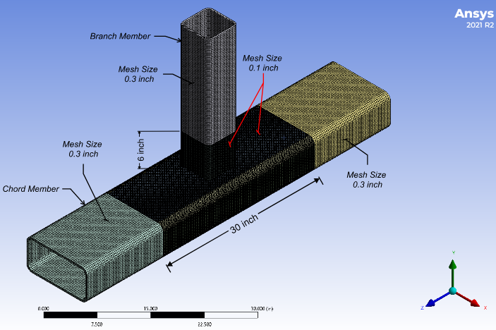
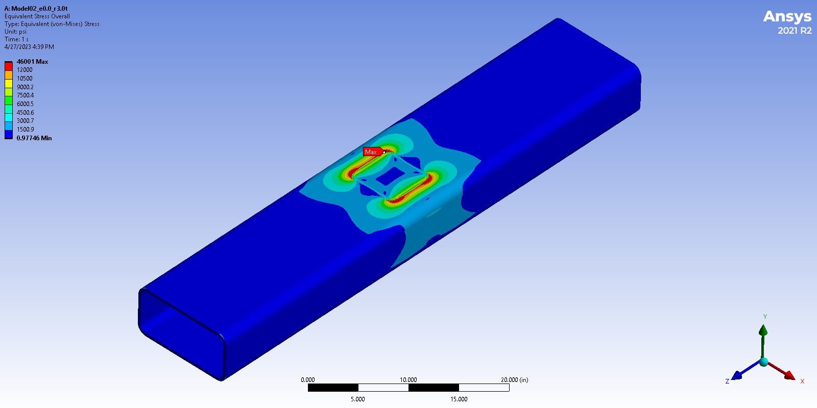
Fig. 5 shows an example stress contour with a maximum stress (von Mises) of 46000 psi (317 MPa) in the chord wall under the onset yield load. Note that, in this study, the branch-to-chord width ratios (β) for Config. 1 and Config. 2 are 0.5 and 0.67, respectively. For a width ratio β ≤ 0.85, the chord wall plastification occurs when the branch member is subjected to a bending moment, which causes the tension and compression loads transferred through the chord wall (which is relatively flexible) [10].
3. Effect of branch length
The Config. 1 in Table 1 was used to examine the influence of branch length on the onset yield moment of the connection. Two different cases were studied: one with a chord length of 7.5 ft (2.29 m) and a branch length of 2 ft (0.61 m), while the other with a chord length of 7.5 ft (2.29 m) and a branch length of 3 ft (0.914 m); for both models the corner radius is three times the member thickness (i.e., r=3t). The results of onset yield moments are shown in Fig. 6. As can be seen, the change in branch length has minimal effect on the onset yield moment of the HSS-to-HSS connection with or without eccentricity. Note that the onset yield moment was defined as the onset yield load multiplied by the branch length [6]; when the connection had a larger branch length, the onset yield load decreased, giving approximately the same onset yield moments.
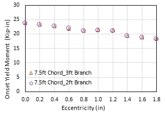
(Note: 1 in = 25.4 mm; 1 Kip-in = 0.113 kN-m)
4. Effect of chord length
The Config. 1 in Table 1 was again used to examine the influence of chord length on the onset yield moment of the connection. Three different cases were studied: the first one is with a chord length of 2.5 ft (0.76 m) and a branch length of 1 ft (0.305 m) (which is the model in the refined analyses in [6]); the second one is with a chord length of 5 ft (1.52 m) and a branch length of 2 ft (0.61 m) (which is the model in the preliminary analyses in [6])); the third one is with a chord length of 7.5 ft (2.29 m) and a branch length of 2 ft (0.61 m). All models have a corner radius equal to three times the member thickness (i.e., r=3t). The results of onset yield moments are shown in Fig. 7. As can be observed, when changing chord length from 7.5 ft (2.29 m) to 5 ft (1.52 m), the onset yield moments remain almost the same; however, when changing chord length from 5 ft (1.52 m) to 2.5 ft (0.76 m), the onset yield moments increase by up to 8%.
Also, when the connection eccentricity increases from zero to 1.8 in (45.7 mm), the onset yield moments decrease by 23.4%, 25.0%, and 23.2% for the 2.5 ft (0.76 m), 5 ft (1.52 m), and 7.5 ft (2.29 m) models, respectively. Note that, for the model of a chord length of 2.5 ft (0.76 m), 0.1 in (2.54 mm) mesh size was used for the entire model. It is worth mentioning that the onset yield moment decreased by approx. 25% when the connection eccentricity increases from zero to 1.8 in (45.7 mm) in the refined analysis of Config. 1 connection in [6], which showed good agreements with the results from this study.
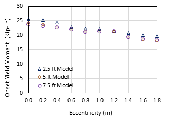
(Note: 1 in = 25.4 mm; 1 Kip-in = 0.113 kN-m)
Based on the observations from the study above on the effects of branch and chord lengths, a chord length of 5 ft (1.52 m) with a branch length of 2 ft (0.61 m) was chosen for further studies on the effect of connection eccentricity on the capacity of HSS-to-HSS moment connections, as discussed in the next section.
5. Effect of connection eccentricity
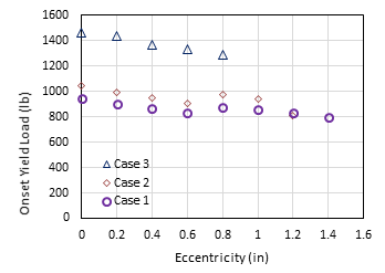
A total of 55 HSS-to-HSS moment connections were modelled in this study by varying the connection eccentricity and the section corner radius. Fig. 8 and Fig. 9 show the onset yield load vs. connection eccentricity for Config. 1 and Config. 2, respectively.
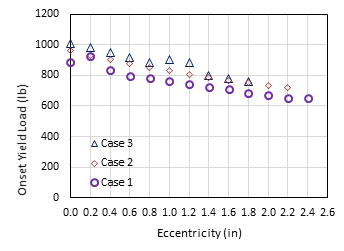
(Note: 1 in = 25.4 mm; 1 lb= 4.45 N)
(Note: 1 in = 25.4 mm; 1 lb= 4.45 N)
For each configuration, three cases were considered by varying the section corner radius, i.e., Case 1 (r =1.6t), Case 2 (r =2t), and Case 3 (r =3t). Overall, it was observed that the onset yield load decreases as the connection eccentricity increases for all cases. Note that the eccentricity of the connection was increased by an increment of 0.2 in (5.08 mm) from the centreline of the chord member to explore the effects of connection eccentricity; in this study, the flange of the branch member doesn’t exceed the starting of curvature of the corner bevel of the chord, which governs the maximum eccentricity (emax) that can be allowed for each connection. The maximum eccentricities for Cases 1, 2, and 3 in Config. 1 are 2.4 in (60.96 mm), 2.2 in (55.88 mm), and 1.8 in (45.72 mm), respectively; whereas the maximum eccentricities for Cases 1, 2, and 3 in Config. 2 are 1.4 in (35.56 mm), 1.2 in (30.48 mm), and 0.8 in (20.32 mm), respectively, as can be seen from Figs. 8 and 9. Due to the different maximum eccentricities for different cases, the eccentricity was normalized to the maximum eccentricity (i.e., e/emax); then the onset yield loads were plotted against e/emax [6], as shown in Figs. 10 and 11.
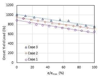
(Note: 1 lb= 4.45 N)
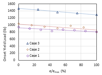
(Note: 1 lb= 4.45 N)
A linear trendline from the best curve fitting was added for each case, shown as the dash lines in Figs. 10 and 11. It can be observed that, for both configurations, the onset yield load decreases with an increase in connection eccentricity. For Config. 1 (see Fig. 10), the rates at which the onset yield load decreases with eccentricity are almost the same for all cases regardless of changes in corner radius; the reductions of onset yield load from the concentric position (e/emax=0%) to the maximum eccentric position (e/emax=100%) are approximately 25-30% for the three cases based on the trendlines. In addition, the case with a larger corner radius gives a higher onset yield load at the same percent of e/emax. Fig. 11 shows the trends of reduction in onset yield load for Config. 2; the trendlines are almost parallel to each other, and the onset yield loads reduce by approximately 12-16% from the concentric position (e/emax=0%) to the maximum eccentric position (e/emax=100%). Like Config. 1, the case with a larger corner radius tends to give a higher onset yield load at the same percent of e/emax. When the corner radius increases, the span of the chord wall decreases which could reduce the flexibility of the chord wall; this appears to be the reason why a higher onset yield load was observed for the connection with a larger corner radius.
It is worth noting that the width ratios are 0.5 and 0.67 for Config. 1 and Config. 2, respectively. It can be seen from Figs. 10 and 11, for the same case of corner radius, the connection with a higher width ratio (β) tends to have a higher onset yield load at the same percent of eccentricity (i.e., e/emax). When the width ratio increases, the top and bottom walls (flanges) of the branch member get close to the corner of the chord member where it could be less flexible [10], which may attribute to the observation that a larger width ratio yields a higher onset yield load.
6. Conclusion
In this paper, a total of 55 HSS-to-HSS moment connections subjected to out-of-plane loading were numerically analysed via finite element modelling. The effects of connection eccentricity and section corner radius were examined for two configurations with different branch-to-chord width ratios. Based on the research findings from this study, the following conclusions could be made for an HSS-to-HSS connection under out-of-plane loading, as follows:
- The onset yield load of a connection decreases as the connection eccentricity increases, regardless of section corner radius and width ratio.
- For a connection with a width ratio of 0.5 (β=0.5), the onset yield load decreases by approx. 25-30% as the eccentricity increases from 0% to 100% of its maximum eccentricity; the decreasing rates of onset yield load are almost the same regardless of corner radius.
- For a connection with a width ratio of 0.67 (β=0.67), the onset yield load decreases by approx. 12-16% as the eccentricity increases from 0% to 100% of its maximum eccentricity; the decreasing rates of onset yield load are almost the same regardless of corner radius.
- For connections with the same configuration, a larger corner radius tends to give a higher onset yield load at the same percent of eccentricity (i.e., e/emax).
- For connections with the same corner radius, a larger width ratio tends to give a higher onset yield load at the same percent of eccentricity (i.e., e/emax).
The research findings above provide valuable insight as to the design of HSS-to-HSS moment connections under out-of-plane loading. It is recommended that the effects of corner radius, width ratio, and connection eccentricity be considered when designing an HSS-to-HSS connection for out-of-plane loading. Further research on other configurations and some experimental studies are suggested.
References
[1] M. Fadden and J. McCormick, "HSS-to-HSS seismic moment connection performance and design," J. Constr. Steel Res, 101, 373-384, 2014.
View Article
[2] S. R. S. Kumar and D. V. P. Rao, "RHS beam-to-column connection with web opening-experimental study and finite element modelling," J. Constr. Steel Res, 62, 739-746, 2006.
View Article
[3] M. Fadden and J. McCormick, "Cyclic quasi-static testing of hollow structural section beam members," J. Structural Engineering, 138 (5), 561-570, 2012.
View Article
[4] J. A. Packer, "Moment connections between rectangular hollow sections," J. Constr. Steel Res, 25 (1-2), 63-81, 1993.
View Article
[5] M. Fadden and J. McCormick, "Finite element model of the cyclic bending behavior of hollow structural sections," J. Constr. Steel Res, 94, 64-75, 2014.
View Article
[6] T. Packman, "The Effects of Eccentricity on Rectangular Hollow Structural Section Stress in Moment Connections Loaded Out-of-Plane," Master's Thesis, Dept. of Civil Engineering, Southern Illinois University, Edwardsville, IL.
[7] American Society for Testing and Materials (ASTM), "Standard Specification for Cold-Formed Welded Carbon Steel Hollow Structural Sections (HSS)," A1085/A1085M-15, West Conshohocken, PA.
[8] ANSYS Workbench 2021 R2, (Software), ANSYS, Inc., Canonsburg, PA.
[9] AISC (American Institute of Steel Construction), "Specification for structural steel buildings," ANSI/AISC 360-10, Chicago, IL.
[10] J. McCormick, "Square and rectangular HSS-TO-HSS moment connections", https://steeltubeinstitute.org/resources/square-rectangular-hss-hss-moment-connections/.
[1] M. Fadden and J. McCormick, "HSS-to-HSS seismic moment connection performance and design," J. Constr. Steel Res, 101, 373-384, 2014. View Article
[2] S. R. S. Kumar and D. V. P. Rao, "RHS beam-to-column connection with web opening-experimental study and finite element modelling," J. Constr. Steel Res, 62, 739-746, 2006. View Article
[3] M. Fadden and J. McCormick, "Cyclic quasi-static testing of hollow structural section beam members," J. Structural Engineering, 138 (5), 561-570, 2012. View Article
[4] J. A. Packer, "Moment connections between rectangular hollow sections," J. Constr. Steel Res, 25 (1-2), 63-81, 1993. View Article
[5] M. Fadden and J. McCormick, "Finite element model of the cyclic bending behavior of hollow structural sections," J. Constr. Steel Res, 94, 64-75, 2014. View Article
[6] T. Packman, "The Effects of Eccentricity on Rectangular Hollow Structural Section Stress in Moment Connections Loaded Out-of-Plane," Master's Thesis, Dept. of Civil Engineering, Southern Illinois University, Edwardsville, IL.
[7] American Society for Testing and Materials (ASTM), "Standard Specification for Cold-Formed Welded Carbon Steel Hollow Structural Sections (HSS)," A1085/A1085M-15, West Conshohocken, PA.
[8] ANSYS Workbench 2021 R2, (Software), ANSYS, Inc., Canonsburg, PA.
[9] AISC (American Institute of Steel Construction), "Specification for structural steel buildings," ANSI/AISC 360-10, Chicago, IL.
[10] J. McCormick, "Square and rectangular HSS-TO-HSS moment connections", https://steeltubeinstitute.org/resources/square-rectangular-hss-hss-moment-connections/.