International Journal of Civil Infrastructure (IJCI)
ISSN: 2563-8084

Volume 6 - Year 2023- Pages 67-75
DOI: 10.11159/ijci.2023.009
Optimising Design of Lime Stabilised Temporary Working Platforms
Sandra Misiarz1, Paul Beetham1
1Nottingham Trent University, School of Architecture, Design and the Built Environment
50 Shakespeare Street, Nottingham, Nottinghamshire, United Kingdom NG1 4FQ
sandra.misiarz2017@my.ntu.ac.uk; paul.beetham@ntu.ac.uk
Abstract - Working platforms are temporary geotechnical structures that provide stability to heavy plant on construction sites. Traditionally made from granular unbound material of sufficient thickness, platforms are implemented where the natural ground is not strong enough to support imposed loads. To reduce the depth of minimum required fill, hydraulically bound materials (HBM) can be used. However, there is no design guidance on HBM working platforms as any available methods were developed for purely granular material. This paper considers the case of HBM platforms of varied thicknesses made from lime treated Mercia Mudstone (MMG). The platforms were designed under the industry approved methods and the outputs were analysed using Discontinuity Layout Optimization software. The analysis included comparison between the bearing capacity of granular platforms and HBM of different strength parameters. Results showed that the industry design methods are heavily reliant on the frictional angle of platform material, and they could not properly account for strength of HBM which mobilise substantial strength through cohesion. Although the granular platform design obtained through these methods aligned well with the DLO analysis, they were found to underestimate bearing capacity of HBM platforms when compared to the software. Further DLO analysis showed that the granular platforms had much lower bearing capacity than that of HBM. In the scenarios considered, even adding 0.75% of lime had the potential to decrease the required platform depth to 0.1m (although such a large reduction is not recommended with the design guidance limit advised as 0.3m), compared to 0.7m which would be required if a granular platform was used. It is concluded that future work into the subject with the use of additional analytical software method, while considering the strength of the subgrade as another variable, would give stronger understanding of how HBM platforms could be designed to the greatest benefit.
Keywords: Working platform, Hydraulically bound material, Discontinuity layout optimization, Lime stabilisation
© Copyright 2023 Authors - This is an Open Access article published under the Creative Commons Attribution License terms. Unrestricted use, distribution, and reproduction in any medium are permitted, provided the original work is properly cited.
Date Received: 2023-08-25
Date Revised: 2023-09-29
Date Accepted: 2023-11-01
Date Published: 2023-11-13
1. Introduction
Working platforms are temporary geotechnical structures that support high, short-term loads from heavy plant on construction sites. They are required where natural ground in place is not strong enough which could lead to dangerous cases of mobile cranes toppling over resulting in injury or death. Traditionally, the platforms are constructed from granular unbound material with thicker platforms being able to provide greater bearing capacity. The formulas used in the design processes originate from shallow foundation design methods, where the system is taken as two soil layers. The stronger platform material can reduce the imposed pressure which is then transferred to the weaker underlying formation [1].
There is no British or European Standard method detailing the design of working platforms, , however, for UK practice there are three industry approved methods. These methods vary in complexity and how design robustness is achieved e.g., through partial factors, but each approach determines the minimum platform thickness [2].
From the author’s experience, the most widely used method for the design of working platforms in the UK is BR 470 [3]. Its semi-empirical approach was developed from Meyerhof’s experimental model for a footing punching through a strong platform material overlying a weak subgrade [3]. This assumes the platform provides punching shear resistance, supporting some of the applied load and reducing bearing pressure on the formation. The model does not account for the weight of the platform material or any benefit from surcharge and assumes no lateral shear strength occurs at the formation level [1].
The second and lesser used method, CIRIA Special Publication 123 (SP123), instead considers lateral stresses within the platform material assuming that the pressure applied by the tracked plant is spread through the platform at a load spread angle and applied to the formation level over a wider area [4]. The vertically applied load develops horizontal stresses within the platform fill, causing a horizontal thrust in the platform material which is partially supported by passive resistance. As this resistance is limited by the low self-weight of fill, the reduced horizontal stress is transferred onto the clay subgrade as an outward shear stress [4].
The third design method is the Temporary Works forum (TWf) model which is similar in concept to SP123 by accounting for horizontal shear on the formation, except it expands on this model through use of other accepted geotechnical methods. For example, it adapts Boussinesq theory to derive a nominal effective area so that the pressure on the subgrade is not underestimated. The method is heavily based on the use of charts, making it a much more involved, time-consuming process with more scope for user error [1].
All the above methods have been derived for platforms composed of high quality unbound granular material which generate shear strength from frictional behaviour. Assuming absence of deleterious components e.g. high organic or sulphate sources, a wide range of site won material can be improved with binders to produce a Hydraulically Bound Material (HBM) [5]. HBM are mixtures which set and harden under hydraulic reactions with lime and cement being common treatments for cohesive fills. The main purpose of the binder is usually to modify wet material to an optimum moisture content for compaction and promote further strength gain with physico-chemical changes to the clay particle structure and progressive development of cementitious bonds with prolonged curing [6]. As the binders can improve the natural ground in place, import requirements can be minimised, making it a sustainable alternative to unbound granular material [6]. As HBMs generate strength in a fundamentally different way to unbound granular material, the use of industry design methods has proven difficult in practice. As the most common strength test methods for HBMs comprise Unconfined Compressive Strength (UCS) or California Bearing Ratio (CBR), there is difficulty in determining appropriate input design parameters to use in above noted design methods. This difficulty in knowing how to link the determined strength to the design method applies a constraint to these sustainable working platforms from being widely adopted.
Discontinuity Layout Optimization (DLO) is a limit analysis method which has the potential for being successfully implemented in working platform design, as it has been previously applied to embankments with and without geogrid reinforcement [7], as well as unbound working platform problems reinforced with geogrids [8]. The method uses the perfect plasticity model with an upper bound yield to determine kinematically admissible mechanisms of plastic collapse. Optimization techniques then identify the critical layout of discontinuities at collapse [7]. DLO can incorporate the Mohr-Coulomb strength model to determine the resistance generated along the failure planes at collapse and is therefore able to include parameters relevant to HBMs, specifically the angle of shearing resistance (j’), and cohesion, (c’) for effective stress analysis, or cohesion undrained (Cu) in a total stress analysis.
This paper presents the results of HBM working platforms designed through industry methods and compares them to the outputs of DLO analysis. The comparisons between the strength of granular platforms and their HBM equivalents are also discussed, highlighting the benefits of lime treatment in context of temporary platforms.
2. Methodology
The general approach taken was (1) Carry out working platform designs using data for stabilised and well graded granular material following the three industry approved methods, (2) conduct a DLO analysis of the designed platforms, and (3) compare and contrast the industry methods vs DLO outputs.
2. 1. Material Properties
The method assumed the case of a single, deep layer of cohesive subgrade underlying a working platform. Four different platform materials were considered, one granular type and HBMs of different lime contents and cure periods. Material parameters for the granular fill considered were taken from the BR470 industry guidance document [3]. For the HBM, the authors had access to secondary data (from a larger research project delivered in collaboration with Balfour Beatty Vinci) which included extensive commercial lab results on 100mm diameter triaxial test specimens for a lime treated fill of Mercia Mudstone Group (MMG) weathering grade 4a. The soil samples were treated with 0%, 0.75%, 1.5% and 3.0% of lime and were tested in a multistage consolidated undrained triaxial test, using cell pressures of 50, 250 and 500kPa and after lab temperature curing for 28, 90 and 180 days. Compaction of all fill specimens used standard (2.5kg) proctor compactive effort at a moisture content between 1.05 to 1.1 times the Optimum Moisture Content (a moisture condition deemed generally suitable for placement of such fill by the separate ongoing study). The parameters for the subgrade material were also taken from site data with a cohesion undrained taken as the characteristic value for insitu MMG grade 4a. Table 1 summarises all the material properties and it can be seen from the data that the effect of lime treatment is to cause a significant increase in j’ and substantial increases to c’. Both j’ and c’ show a general increase with prolonged cure and higher binder addition, which is most pronounced in the latter with the 180-day 3% specimens having a c’ of 165kPa; 11 times greater than untreated.
Table 1. Material parameters used in this study.
|
Material |
Unit Weight (kN/m3) |
j’ (°) |
c' (kN/m2) |
|
Untreated MMG (to indicate the change caused by lime treatment) |
20.9 |
35 |
15 |
|
HBM 0.75% lime @28 days |
20.3*1 |
43.8 |
39.4 |
|
HBM 0.75% lime @90 days |
43.5 |
47.2 |
|
|
HBM 0.75% lime @180 days |
45.7 |
58.7 |
|
|
HBM 1.5% lime @28 days |
20.1*1 |
42.6 |
38.2 |
|
HBM 1.5% lime @90 days |
40.3 |
56.9 |
|
|
HBM 1.5% lime @180 days |
45 |
95.9 |
|
|
HBM 3.0% lime @28 days |
18.9*1 |
47.5 |
75.7 |
|
HBM 3.0% lime @90 days |
44 |
150 |
|
|
HBM 3.0% lime @180 days |
48 |
165 |
|
|
Granular platform |
20 |
40 |
- |
|
MMG subgrade*1*2 |
20.89 |
- |
- |
|
Note: *1 Derived from bulk density at 28 days cure. *2 Cohesion undrained, Cu=75 kN/m2. |
|||
2. 2. General Design Approach
The general approach using the three industry methods was to:
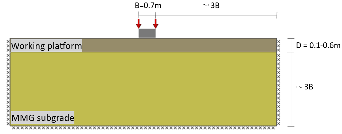
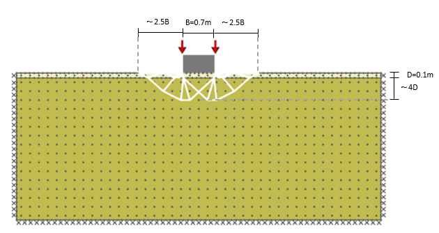
- Assume the working platform would be loaded by the plant track with breadth 0.7m and length 3.1m. Use the industry method and the material parameters in table 1, to calculate the design resistance of a working platform for thicknesses between 0.1 and 0.6m using 0.1m intervals. These calculations included the partial factors relevant to the method as summarised in table 2.
- LimitState:GEO software was used to set up a model simulating the same 0.7m wide track (see figure 2 and further details on the model set up are given below in section 2.4). The resistance calculated by the industry method was input as the characteristic loading onto the simulated track, which required that the design resistance was divided by the partial factor for the variable action (as relevant to the method followed; table 2) to produce this characteristic load.
- The software would undertake a DLO equivalent analysis of each industry method to determine the failure mechanism and the associated collapse load. The software included options to include the same partial factors for the materials and actions as used for each method (table 2).
- An adequacy factor of the DLO equivalent model is determined i.e., DLO equivalent resistance / industry method resistance. An adequacy factor of 1 would mean the methods output the same resistance, whereas a factor >1 would mean the DLO method has calculated proportionally higher resistance and vice versa.
Table 2. Design partial factors.
|
Design method Design parameter |
BR470*1 |
TWf*1 |
CIRIA SP123 |
|
Variable action |
1.2 |
1 |
1.14 |
|
Angle of internal friction |
1 |
1.25 |
1.25 |
|
Cohesion undrained |
1 |
1.4 |
1.25 |
|
Effective cohesion *2 |
1 |
1.25 |
1.25 |
|
Note: *1Assuming load case 2. *2 Value not explicitly specified in design guidance and so consistency with the source document was used i.e., unity for BR470, EC7DA1 Comb 2 for TWf and 1.25 for SP123. |
|||
2. 3. Industry Design Approach
Calculation spreadsheets were implemented for all methods, each in accordance with their published methodology. Separate resistances were output for granular and then the HBM material properties as specified in table 1. As each of these industry methods were developed for platforms made from granular materials, this meant they were characterised only by j’ and weight density. Thus, j’ had a significant effect on the design resistance determined. This was evident in the design equations, which for brevity are not fully reproduced from the published methods (that are accessible to any interested party), but as an example from the BR 470 method [3] the expression for bearing resistance for cohesive subgrade and as modified by the working platform is:

Where:
R is bearing resistance of a platform in kN/m2
cu is undrained cohesion of the subgrade in kN/m2
Nc is the bearing capacity factor for cohesive subgrade
sc and sp are shape factors
D is the thickness of platform material in m
γp is bulk weight density of platform in kN/m3
W is the track width in m
Kptanδ is the punching shear resistance coefficient
The punching shear resistance coefficient (Kptanδ) was a function of the angle of shearing resistance of granular platform material (j’), where δ=2/3j’, as presented in figure 1.
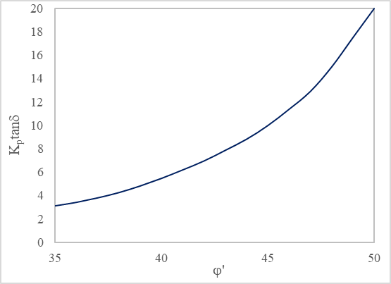
Figure 1 demonstrates the relationship used in BR 470 is very sensitive to changes in j’ of the platform fill [2] and the TWf and SP123 methods have similar reliance on j’, without scope to account for strength increase relating to the drained cohesion intercept, c’. This highlights the difficulty of using such methods to account for how HBM platforms develop strength and these analyses for the HBM could only include the j’ values in table 1.
2. 4. DLO Analysis and Comparison with Industry Methods
The DLO analysis was undertaken using software LimitState:GEO 3.6 with the baseline model as per figure 2. The model boundaries were initially set up as per published guidance for Finite Element Analysis [10] and then initial analyses checked to ensure the failure mechanism was not in contact with the model boundaries [8] and this did require some alterations to those indicated in figure 2. The analysis was conducted under fine nodal resolution to obtain more accurate results [8]. The 0.7m wide track was modelled as a rigid footing through which the design load was applied. As the model accounts for friction between the underside of the track and the platform, a conservative assumption made was that half of platform frictional strength would be utilised at this interface. Due to lack of available guidance, no shape factors were included in the model [8], and the track was assumed as a continuous footing; a conservative assumption.
3. Key Findings and Discussion
3. 1. Comparison of industry methods with DLO analysis for granular platforms
Figure 3 shows the DLO adequacy factor as undertaken on platform thicknesses ranging from 0.1m to 0.6m and using parameters for a granular platform. This provides a direct assessment of how the DLO method compares with the three industry approaches. Different observations are noted across the three industry methods, and these are discussed in turn.
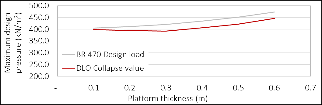
Figure 3 identifies that adequacy factors for the BR470 method ranges between 0.93-0.99 across the 0.1-0.6m platform depths, indicating that DLO outputs are closely aligned (<7% difference). This is supported generally well by figure 4.a, which shows that calculated resistances are broadly similar and there are similar increases in resistance computed by both methods between 0.3m and 0.6m platform. These findings are consistent with a previous study [8] on working platform design which reported that that the BR470 bearing capacity value were within 4% of the collapse values produced with the LimitState:GEO software.
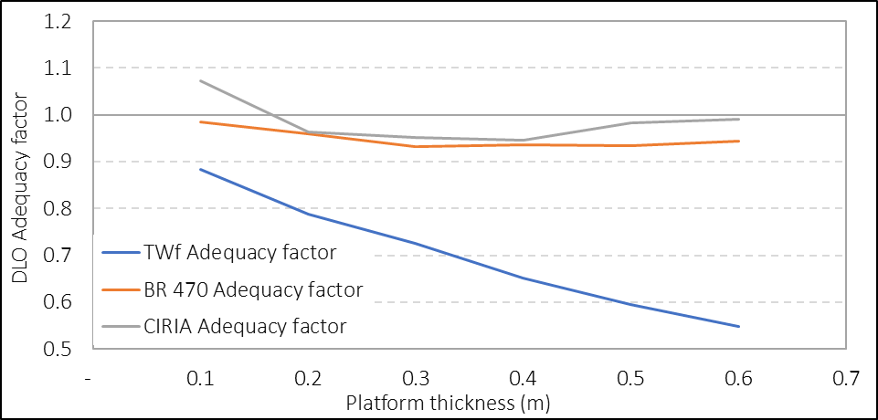
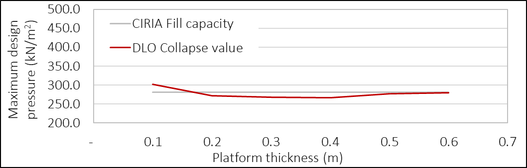
For SP123 the adequacy factors are also relatively closely aligned with a range of 0.95-1.08 (figure 3), suggesting a similar good relationship between this method and the DLO analyses (<8% difference). With regard to resistance calculated, figure 4.b identifies that the SP123 approach shows no increase in resistance with increasing platform depth and the DLO analysis is very similar with only small differences between platform depths and actually the highest resistance is found in the thinnest (0.1m) platform depth. This may seem surprising given the BR470 results, but this type of trend in some working platforms is directly discussed in the CIRIA SP123 publication which on page 243 states “the bearing capacity of the fill may act as a cut off to the envelope of available resistance” [4]. This may well be the case in this work as the characteristicj’ value of 40° used for the platform strength is relatively conservative and then the SP123 method requires it is factored by a factor of 1.25 to a design value of 33.9°. This could also explain why the 0.1m platform recorded the highest resistance, as a greater proportion of the failure planes would pass through the subgrade material, where it appears that the design undrained shear strength contributes more resistance than the equivalent granular platform. It is further noteworthy that for the HBM designs where working platform design strengths were notably higher, this strength cut off did not occur and the expected trend of increasing resistance with platform depth was present and this is discussed further below (section 3.2). Notwithstanding, a good correlation between the SP123 method and the DLO software was established and deemed satisfactory for comparison with HBM going forward.
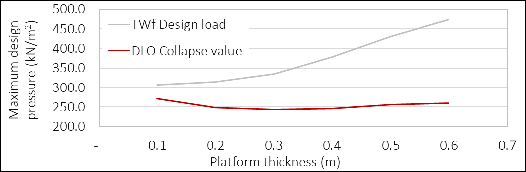
For the TWf method substantially different trends were noted, with an adequacy factor of 0.88 for a 0.1m platform which progressively reduced to 0.55 for a 0.6m platform, thus indicating a relatively poor correlation between the TWf and DLO approaches. Furthermore, figure 4.c clarifies that the reason for the poor correlation is that the TWf method outputs progressively higher resistance with increasing platform thickness. However, as was the case in the SP123 comparison, the DLO equivalent analyses showed little difference in resistance regardless of depth and it appears that a similar situation where the platform shear strength were acting a resistance cut off in these analyses. As there were two discrepancies for this method in the granular material, further use of the TWf method was not considered in this study. Although, with reflection it may have proven that using a higher design friction angle may have shown stronger correlations between the methods; but this was not explored.
In summary, the initial comparison of the DLO outputs with the industry methods identified that the DLO method provided similar outputs to the industry methods indicating the DLO method had potential to quantify the resistance from the cohesive and frictional strength of HBM. Of the two industry methods, SP123 provided more conservative values of maximum bearing pressures, which was due to the partial factors applied to the internal shear angle significantly reducing the bearing capacity factor of that method and also the equivalent DLO resistance [11].
3. 2. Comparison of industry methods with DLO analysis for HBM platforms
Through undertaking the initial designs following the BR470 and SP123 methods, it was noticed that there was generally a consistent increase in the resistance of the HBM platforms in comparison to the granular equivalents. This was in line with the HBM having a higher j’ than the value selected for granular fill (table 1). However, as the published methods had no way to include the c’ of the material, the increases were relatively small and there was not a significant difference in resistance between the higher lime content or longer curing times. This is not considered true for the real performance of HBMs where both longer curing and higher binder dosage impart substantial benefit. [6].
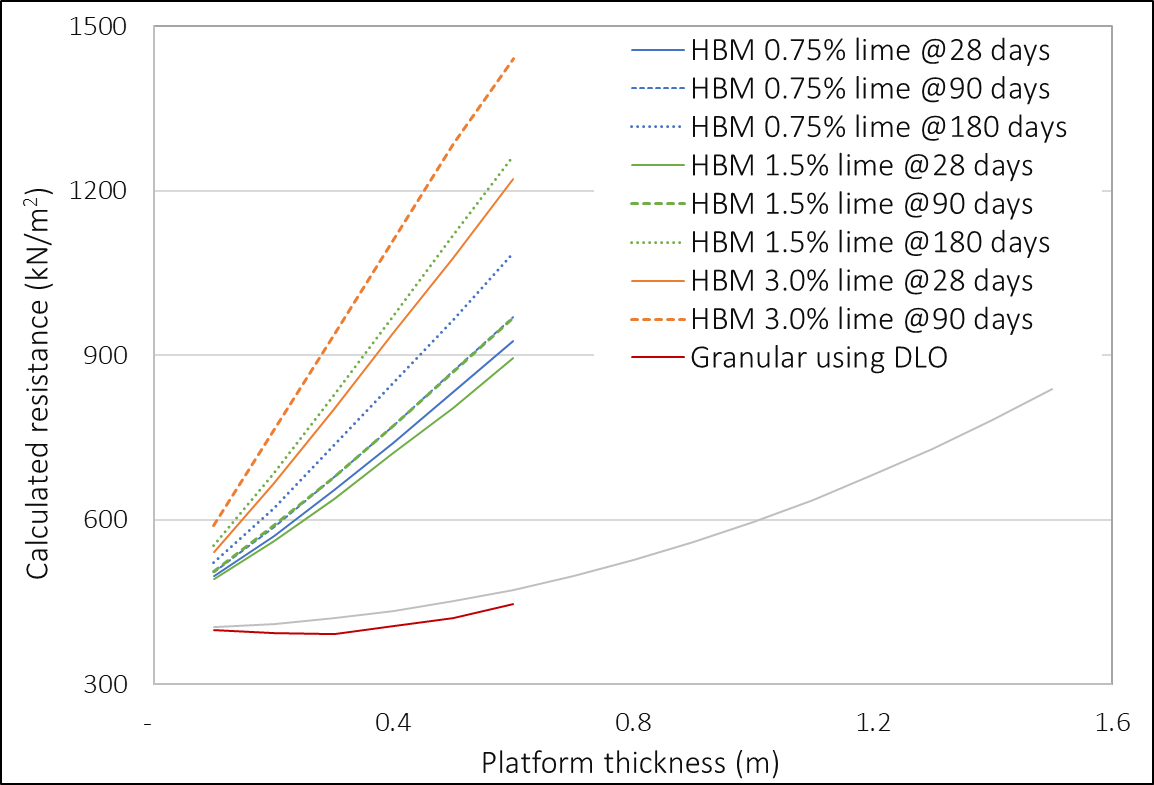
DLO analysis of the HBM working platforms using the BR470 partial factors are shown in figure 5 and this shows substantial increases in resistance that results from including both the c’ and j’ of these materials compared with the granular equivalent. As an example, for a 0.3m deep platform, the granular DLO analysis calculates a resistance of 392kN/m2, whereas for 1.5% lime cured for 28 days this is 1.6 times greater at 639kN/m2. The effect of higher lime and longer curing is reflected in the results with 0.3m deep platform of 3% lime cured for 90 days with 937kN/m2 resistance i.e., 2.4 times greater than the granular platform. The increasing difference in resistance between the lower lime / shorter cures and higher lime / longer cures highlights the influence of the strength contribution from cohesion in the latter.
Figure 5 indicates that even the mixtures with the smallest portion of lime at the shortest cure times (0.75% and 28 days) had the potential to reduce the platform thickness from 0.7m to 0.1m for the same amount of resistance, i.e., 500kN/m2. Thus, replacing the granular fill with HBM would have a great economic and environmental gain should an appropriate design method were implemented. However, it should be noted that the BR470 recommends the minimum temporary platform depth should be 300mm as shallower depths are unlikely to have a significant impact on bearing resistance [3].
Nevertheless, even with this imposed minimum of 300mm the use of any HBM would have the potential to increase the bearing capacity of a 0.3m thick platform by at least 1.6 times comparing to unbound material of same thickness and the benefits increase further with greater platform depth, higher binder addition and longer curing. While not directly considered in this study, similar benefits should be apparent with other HBMs such as cement stabilised soils, which would have further benefits of achieving the higher shear strengths much sooner e.g., within 7 days.
3. 3. Comparison of DLO failure planes of granular and HBM platforms
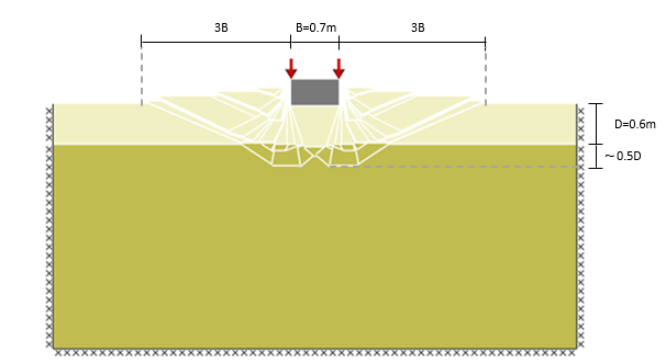
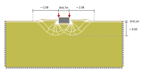
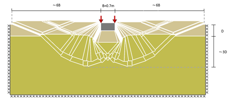
The analysis of the failure modes in working platforms computed by the DLO software show that platforms made from the stabilised material develop a different failure shape compared to granular platforms. The computed failure mode shapes of stabilised platforms were wider and deeper, which is shown in figure 6a-d, where the failure shape extent was measured relative to the track width of 0.7m and to the depth of the platform. For the purpose of comparison, the cases of a granular platform of depth 0.1m and 0.6m as well as a platform stabilised with 3% of lime and cured for 28 days of same thicknesses were considered. It is noteworthy that as the software magnifies displacements at the surface this helps visualise the collapse mode [8], and this helps identify the volume of soil affected by the failure to relate this to footing breadth (B) or stabilised platform depth (D) as shown in figures 6a-6d.
Figure 6a shows a 0.1m thick granular platform at failure, where most of the failure plane translates into the ground by a maximum depth of approximately 0.5m and a breadth spanning a maximum 4.2m. By comparison the 0.6m deep platform failure mode shape (Figure 6b) is slightly wider at 4.9m and deeper extending down to 0.9m. This means that for the thicker working platform, the vast majority of shear planes will generate resistance within the working platform platform, compared to 0.1m thin platform where most of the failure plane is within the subgrade.
By comparison the 3%lime at 28 days cure platform causes substantial change to the shape of the failure planes. The failure plane from the 0.1m deep platform has the same 4.2m breadth as the granular equivalent however, extends to over twice the depth into the subgrade i.e. 1.05m deep. The effect is even greater for the 0.6m lime treated platform with a breadth of 9.1m and depth down to 2.4m.
The analysis of the computed failure planes described above shows that increasing the platform thickness and opting for stabilised platform material results in mobilising a much larger volume of material, ergo more resistance on the failure plane. This is an informative visualisation of why the thicker, stabilised layers generated the greater strengths reported in figure 5.
4. Conclusions and recommendations for further work
- The SP123 method producing the most conservative bearing capacity values across all granular material and HBM.
- Both BR470 and SP123 industry methods use only thej’ of the platform material to characterise its shear strength and were unable to represent the strength of the HBM which had substantial strength relating to c’.
- DLO equivalent analyses of the BR470 and SP123 methods were able to include both the c’ andj’ of the HBM. Results of the BR470 DLO equivalent indicated all lime treatments achieved design resistance of at least 500kN/m2 from a 0.1m deep platform. To achieve the same resistance, a granular platform of at least 0.7m was required.
- BR470 guidance recommends that the minimum temporary platform depth should be 300mm as shallower depths are unlikely to have a significant impact on bearing resistance. Notwithstanding, even with the 300mm minimal platform depth, a HBM platform would still be less than half as thick as the unbound material design and would have extra over design redundancy.
- Inspection of the failure planes output by the DLO method show that the increased c’ from lime treated platforms cause the planes to propagate wider and deeper; mobilising resistance across a much greater volume of both the working platform and underlying subgrade.
Alternative design methods for temporary working platforms, such as DLO analysis can open up the potential for more economic and sustainable HBM designs, departures from tried and tested, but notably limited, methods must be taken with caution. To add robustness to these study findings further work is recommended to:
- Extend the study scope to include subgrade soils with lower undrained shear strength.
- Consider the reliability / relevance of consolidated undrained triaxial tests to represent the design shear strength of the HBM. Comparisons with strengths from consolidated drained triaxial tests will be useful in this regard
- Compare DLO analysis against outputs from other analytical methods, e.g., Finite Element Analysis software or similar. Including, as relevant different constitutive models to represent the platform shear strength and stiffness.
References
[1] Temporary Works forum, Working Platforms - Design of granular working platforms for construction plant - A guide to good practice. London, TWf, 2019.
[2] D. Egan, J.P. Feest, and G.J. Horgan, "Comparison of Design Approaches for Working Platforms Used for Piling Plant," in Proceedings of the Piling 2020 Conference, London, 2021, pp. 343-348.
[3] Building Research Establishment, Report No 470 Working platforms for tracked plant. Watford, BRE Bookshop, 2004.
[4] R.A. Jewell, "Working platforms and unpaved roads," in Soil reinforcement with geotextiles, R.A. Jewell, Ed. London: CIRIA, 1996, pp. 235-252.
[5] C. Tate, "Site Roads and Working Platforms," in Temporary Works: Principles of Design and Construction, G. Murray and P.F. Pallet, Ed. London: ICE Publishing, 2012, pp. 61-77.
[6] H. Skinner, A. Dunster, R. Harrex and F. Moulinier, Guidance on the use of HBM in Working Platforms. Oxon, The Waste & Resources Action Programme, 2006.
[7] C.C. Smith and A. Tatari, "Limit analysis of reinforced embankments on soft soil," Geotextiles and Geomembranes, vol. 44, no. 4, pp. 504-514, 2016.
View Article
[8] C.C. Smith. (2014, June 5). Working Platform Analysis Using LimitState:GEO (webinar) [Online]. Available: https://www.youtube.com/watch?v=l5D-J658wzg.
[9] S. Hawksbee, C. Smith and M. Gilbert, "Application of discontinuity layout optimization to three-dimensional plasticity problems," in Proceedings of the Royal Society: Mathematical Physical and Engineering Sciences, London, 2013, vol. 469.
View Article
[10] A. Lees, "How is a geotechnical finite element analysis set up," in Geotechnical Finite Element Analysis: A practical guide, A. Less, Ed. London: ICE Publishing, 2016, pp. 1-28.
View Article
[11] B. Attewell, G. Johnstone, M. Larish and R. Damen, "Temporary working platforms - technical guidance on New Zealand Good Practice", in NZGS Symposium, Auckland, 2020, vol. 21.
[1] Temporary Works forum, Working Platforms - Design of granular working platforms for construction plant - A guide to good practice. London, TWf, 2019.
[2] D. Egan, J.P. Feest, and G.J. Horgan, "Comparison of Design Approaches for Working Platforms Used for Piling Plant," in Proceedings of the Piling 2020 Conference, London, 2021, pp. 343-348.
[3] Building Research Establishment, Report No 470 Working platforms for tracked plant. Watford, BRE Bookshop, 2004.
[4] R.A. Jewell, "Working platforms and unpaved roads," in Soil reinforcement with geotextiles, R.A. Jewell, Ed. London: CIRIA, 1996, pp. 235-252.
[5] C. Tate, "Site Roads and Working Platforms," in Temporary Works: Principles of Design and Construction, G. Murray and P.F. Pallet, Ed. London: ICE Publishing, 2012, pp. 61-77.
[6] H. Skinner, A. Dunster, R. Harrex and F. Moulinier, Guidance on the use of HBM in Working Platforms. Oxon, The Waste & Resources Action Programme, 2006.
[7] C.C. Smith and A. Tatari, "Limit analysis of reinforced embankments on soft soil," Geotextiles and Geomembranes, vol. 44, no. 4, pp. 504-514, 2016. View Article
[8] C.C. Smith. (2014, June 5). Working Platform Analysis Using LimitState:GEO (webinar) [Online]. Available: https://www.youtube.com/watch?v=l5D-J658wzg.
[9] S. Hawksbee, C. Smith and M. Gilbert, "Application of discontinuity layout optimization to three-dimensional plasticity problems," in Proceedings of the Royal Society: Mathematical Physical and Engineering Sciences, London, 2013, vol. 469. View Article
[10] A. Lees, "How is a geotechnical finite element analysis set up," in Geotechnical Finite Element Analysis: A practical guide, A. Less, Ed. London: ICE Publishing, 2016, pp. 1-28. View Article
[11] B. Attewell, G. Johnstone, M. Larish and R. Damen, "Temporary working platforms - technical guidance on New Zealand Good Practice", in NZGS Symposium, Auckland, 2020, vol. 21.