International Journal of Civil Infrastructure (IJCI)
ISSN: 2563-8084

Volume 7 - Year 2024- Pages 21-31
DOI: 10.11159/ijci.2024.003
Assessment of Seismic Responses of a Base-Isolated Rectangular Fluid Tank with a Bottom Mounted Vertical Baffle under an Irregular Excitation
Jyoti Ranjan Barik1, Kishore Chandra Biswal1
1National Institute of Technology Rourkela, Department of Civil Engineering
Odisha, India 769008
519ce1001@nitrkl.ac.in; kcb@nitrkl.ac.in
Abstract - The present numerical exploration involves the assessment of the dynamic responses of a partially filled rectangular fluid container decoupled by nonlinear hysteretic bearings. The computational domain exhibits a bottom mounted submerged vertical baffle and is simulated using Galerkin's finite element method based on the velocity potential. The developed model's accuracy is authenticated by comparing with the existing results. The time domain analysis involves a long-duration irregular harmonic motion subjected to the system. The findings suggest that the isolation system is remarkably effective across various tank-fluid-baffle setups and efficiently controls key dynamic responses in the fluid tank, including hydrodynamic base shear and sloshing amplitudes. The investigation also evaluates the peak hydrodynamic responses in tanks with and without base isolation, considering different heights and widths of the submerged baffle. It has been found that changes in the h/d ratio have a more significant impact on sloshing amplitude and base shear responses than changes in the w/L ratio. The implementation of base isolation leads to a reduction in sloshing amplitudes ranging from 12% to 34% across different baffle configurations, with the exception being at h/d=0.5. Additionally, base shear is reduced by 2% to 48% in tanks with base isolation, depending on the specific baffle configurations. Notably, the maximum isolator displacement consistently occurs at h/d=0.5, regardless of the baffle width.
Keywords: Nonlinear hysteretic bearings, Galerkin’s finite element method, submerged baffle, long-duration irregular harmonic motion.
© Copyright 2024 Authors - This is an Open Access article published under the Creative Commons Attribution License terms. Unrestricted use, distribution, and reproduction in any medium are permitted, provided the original work is properly cited.
Date Received: 2023-12-15
Date Revised: 2024-04-29
Date Accepted: 2024-05-01
Date Published: 2024-05-31
1. Introduction
Liquid storage tanks play a crucial role in diverse fields such as public infrastructure, industries, and nuclear facilities. The movement of liquid's free surface in response to external disturbances is commonly known as sloshing. This phenomenon significantly affects the dynamic properties of liquid storage tanks under external forces, exerting control over their behavior. Because of the intensive hydrodynamic pressure induced by sloshing, tanks used for storing different chemicals, fuels, and water are prone to significant damage during earthquakes. As a result, the potential damage to these containers brings risks such as fire outbreaks and contamination, leading to various societal issues [1]. Thus, studying the sloshing behavior in partially filled containers has become a top priority.
To mitigate the negative impact of liquid sloshing, internal baffles are being employed as anti-sloshing mechanisms in partially filled containers. Numerous researchers have conducted numerical investigations to understand the role of submerged baffles in containers, which has notably influenced the dynamic characteristics of liquid sloshing [2]- [4]. Numerous studies have explored the impact of various configurations of vertical baffles in reducing sloshing pressure through experimental approaches [5], [6]. Jiang et al. [7], [8] scrutinized the efficacy of internal baffles in dampening the tank's sway motion, particularly when interacting with internal sloshing flow under wave-induced conditions. Overall, the literature reviewed primarily addressed sloshing responses under regular excitations or typical wave actions. However, real-world liquid containers may encounter irregular external forces. The hydrodynamic behavior of sloshing responses under irregular motion is notably more complex than under regular excitation, necessitating a deeper understanding and investigation. Concentrating this perspective, several studies have emphasized on the impact of different irregular excitations on liquid sloshing issues in ground-supported tanks [9]- [11].
In certain cases, solely relying on internal components to reduce liquid sloshing intensity may not adequately enhance the seismic performance of liquid containers. Hence, the use of base isolation techniques stands out as one of the most effective methods for improving dynamic behavior during significant events. The effectiveness of base isolation has been thoroughly investigated by numerous researchers [12]- [14]. Shrimali and Jangid studied the performance of base-isolated liquid storage tanks utilizing friction-based isolator systems during actual earthquake events [15]. They also evaluated the effectiveness of a New Zealand (NZ) bearing system in managing seismic factors [16]. Their findings indicated that while increased isolation damping beyond a certain optimal level led to an increase in base shear, it effectively reduced sloshing occurrences and minimized bearing displacements. Jadhav and Jangid investigated the performance of base-isolated liquid-filled tanks utilizing sliding-type and elastomeric-type bearing systems [17]. In essence, the studies mentioned above primarily employed the lumped mass approach, dividing the liquid into three nodal masses: impulsive, convective, and rigid. However, analyzing liquid containers using a numerical finite element model that considers the entire liquid domain could potentially be more effective.
This study numerically examines the sloshing behavior of a baffled base-isolated rectangular tank under an irregular excitation using a finite element model. Based on the aforementioned discussion, this study extends the previous research focus, which predominantly explored the effects of submerged baffles on sloshing behaviors in ground-supported liquid tanks experiencing irregular excitations. Exploring the influence of an internal baffle in a partially filled base-isolated container under irregular excitations is a relatively novel area that remains inadequately addressed. This aspect is crucial for understanding the irregular motion of liquid sloshing within such structures. Furthermore, existing studies concerning tank-baffle-isolation systems have primarily concentrated on specific baffle dimensions and have been restricted to real seismic excitations. Hence, the current numerical analysis encompasses various baffle configurations, varying both height and width. This research aims to unveil new insights into the sloshing behavior and quantification of hydrodynamic responses such as impulsive and convective components under irregular excitations in both rectangular base-isolated and non-isolated tanks, which is the primary objective of this study.
2. Numerical modeling
Fig. 1 represents a vertically baffled rectangular tank with base isolation, providing a visual depiction of the problem's geometry.
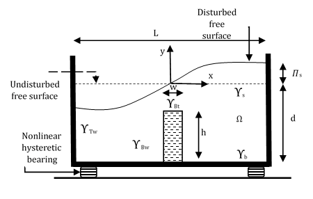
The liquid volume is denoted as Ω, with its boundaries identified as Υs for the free surface, ΥTw for the tank walls, and ΥTb for the tank base. Additionally, the areas of the liquid surface in contact with the baffle's top surface and walls are denoted as ΥBt and ΥBw, respectively. The dimensions of the baffle are varied with the width (w) and height (h). The liquid's density is represented by ρf. The movement of the liquid follows the Laplace equation, assuming the liquid is incompressible, inviscid, and with the flow being irrotational.
2. 1. Boundary conditions
Two boundary conditions are necessary to fully describe the mathematical aspects at the free surface. The kinematic boundary condition dictates that liquid particles remain on the free surface. When disregarding nonlinear components and atmospheric pressure, the unsteady form of Bernoulli's equation is applied to establish the dynamic boundary condition. This yields,
The expression provided above includes the velocity potential function Ф, where µ represents liquid viscosity, and g denotes gravitational acceleration. To establish the boundary condition along the tank and baffle walls, the velocity of the liquid is set equal to the instantaneous wall velocity (Vv) in the perpendicular direction (v). It can be introduced as,

The tank bottom is impermeable, requiring a condition of no flux. This can be expressed as:

2. 2. Mathematical formulation
The liquid domain is meshed using four-noded isoparametric quadrilateral elements. Each node corresponds to a single degree of freedom, specifically a time-dependent potential. (Ф (x, y, t)). It can be defined as,

The shape function Nk is formulated based on natural coordinates. Employing Galerkin's weighted-residual method on the Laplace equation results in,

By applying the integration by parts method using Stoke’s and Green’s theorem to the previous equation, the dynamic equilibrium equation is derived as follows,


The matrices [M] and [C] signify the free surface and damping matrices, respectively. The matrix [K] represents the fluid coefficient matrix, and {F} stands for the force vector. These elements are defined as, ![]() ,
,![]() ,
, ![]() and
and ![]() are the global matrices for different elements.
are the global matrices for different elements.


The values of slosh amplitude (𝛱s), total pressure (Ptot) and total base shear (BStot) are determined through the following equations.


Here nx denotes the unit normal vector in x direction. The hydrodynamic pressure's impulsive component can be isolated and determined separately by disregarding liquid sloshing.

Moreover, the convective component can be derived by subtracting the impulsive component from the total component.
2. 3. Characteristics of nonlinear hysteretic isolator
In this study, the Wen's bilinear hysteretic model is utilized to replicate the nonlinear properties of lead rubber bearings [16]. The empirical relationship between force and deformation is described as:


In the expressions, cb and kb represent the damping and pre-yielding stiffness of the lead rubber isolator. Eq. (17) calculates the natural frequency (ωb) and time period (Tb) of the bearing based on the post-yield stiffness. Meanwhile, the damping ratio (ξb) is determined by Eq. (18). The variables mb and weight W denote the total mass and total weight of the liquid acting on the bearing, respectively. Additionally, the scaled yield strength (F0) is assumed to be 0.05, as per literature findings [16]. Fy and α denote the yield strength (as per Eq. 19) and the ratio of post-yield to pre-yield stiffness (as per Eq. 20) of the isolator. Z represents the non-dimensional hysteretic displacement, governed by a first-order differential equation as outlined in Eq. (21).

In this context, q represents the bearing's yield displacement, while A, n, β, and τ are non-dimensional factors that influence the hysteresis loop's shape. According to literature [16], the bearing parameters remain fixed with A=1, n=2, and q=2.5 cm, whereas the values for β and τ are set to 0.5 in this study. For the present investigation, the period and damping of the bearing are fixed to 3s and 0.2 respectively.
2.4. Equations of motion for the system
The equations that describe the characteristics of the coupled system, consisting of an isolated tank with a vertical baffle, are established as Eqs. (22) and (23).


Fb stands for the restoring force of the isolator, while BS represents the base shear force. Additionally, ![]() and
and ![]() denote the isolator's velocity and acceleration. The velocity and ground acceleration of the excitation are respectively denoted by
denote the isolator's velocity and acceleration. The velocity and ground acceleration of the excitation are respectively denoted by ![]() and
and ![]() respectively.
respectively.
3. Numerical results and discussion
The study involves examining a shallow rectangular liquid tank of 10m × 5m. Within this tank, a vertical baffle is placed at the bottom. The liquid is assumed to have a mass density of 1000 kg/m3. Using MATLAB 2020b software, a finite element algorithm is developed to study the impact of varying the depth of this baffle on a tank decoupled by bilinear hysteretic bearing. The optimal mesh size is determined by the free vibration analysis, particularly focusing on the fundamental period of liquid sloshing. The findings as depicted in Fig. 2 indicate that a mesh size comprising 400 elements (a 20 × 20 grid) would be appropriate for this analysis. In particular, the liquid domain is discretized using 400 numbers of uniform quadrilateral finite elements.
3.1. Verification of the Model
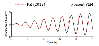
A square tank filled with liquid to a depth of 1m and a width of 1m is excited with a base excitation force defined by ![]() = 0.002 ωf2 sinωft,
where ωf represents the forced frequency considered to be 5.55 rad/s. The sloshing amplitude variation over time is observed at the farthest corner of the right wall, as shown in Fig. 3. The results obtained closely align with a previous solution that utilizes a 2-D meshless local Petrov-Galerkin method from the literature [18].
= 0.002 ωf2 sinωft,
where ωf represents the forced frequency considered to be 5.55 rad/s. The sloshing amplitude variation over time is observed at the farthest corner of the right wall, as shown in Fig. 3. The results obtained closely align with a previous solution that utilizes a 2-D meshless local Petrov-Galerkin method from the literature [18].
3.2. Description of an irregular excitation
To analyze the sloshing response to irregular excitation, it is to develop a time history of the irregular external oscillation. This irregular oscillation can be stochastically modelled by summing a multitude of independent linear harmonic excitations, as outlined below.

In this context, ai represents the ground acceleration amplitude, ranging from 0.002 to 0.05 m/s2. The excitation frequency fi varies from 0.1 to 1 Hz with an increment of 0.1 Hz. Additionally, n denotes the total number of linear sine excitations, which is considered to be 10 for the present analysis. Moreover, the impact of a long-duration irregular excitation on sloshing amplitude, hydrodynamic pressure, and base shear parameters in a vertically baffled rectangular tank is assessed across various depths and widths of the baffle.
3.3. Effect on sloshing amplitude
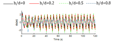
In this section, vertical baffled tank with height-to-depth ratios (h/d) of 0.2, 0.5, and 0.8, as well as width-to-length ratios (w/L) of 0.1 and 0.2, are considered. Figs. 4 and 5 display the time history responses of slosh amplitude for both non-isolated and base-isolated tanks across different width ratios. The results indicate that for the non-isolated tank, the slosh response is dominant at h/d=0.8, whereas for the base-isolated tank, it is dominant at h/d=0.5, among all configurations considered when w/L=0.1. When the width ratio (w/L) is set at 0.2, the sloshing response is significant in the non-isolated tank when h/d=0, as observed in Fig. 4(b). Generally, liquid sloshing is a low frequency oscillating phenomenon. However, lower order frequency components are observed during the early stage of ground motion (i.e., below 20 seconds) relative to the later part, irrespective of the baffle height and width considered, which indicates that the frequency liquid oscillation in ground supported tank is getting amplified in accordance with the duration of the irregular motion.
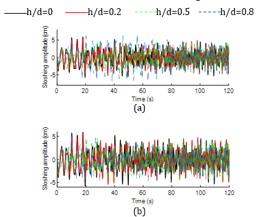
However, the responses in the base-isolated tank remain consistent despite the increase in width ratio, as depicted in Fig. 5. In comparison with the ground supported tank’s responses, the low frequency components are noticed throughout the time history indicating the significant contribution of lead rubber bearing in reducing the frequency of liquid oscillation and such phenomenon is almost consistent during both earlier and later stage of the excitation, irrespective of the baffle configurations.
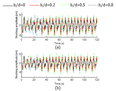
Table 1 presents the maximum sloshing amplitudes for various tank-baffle configurations. It is noted that for the non-isolated tank system, the magnitudes initially decrease and then increase, while the opposite trend is observed for the base-isolated system across all width ratio cases. Moreover, the amplitudes decrease by approximately 12% to 34% when base isolation is applied across various baffle configurations, except at h/d=0.5. This indicates that the use of base isolation generally reduces the liquid sloshing effects, except for h/d=0.5, where the adverse impact on sloshing is observed under the irregular excitation considered, as noticed from Fig. 5. Overall, maximum reduction is noticed in tank without baffle whereas minimal reduction is noticed when both the w/L and h/d ratios of the baffle are 0.2.
Table 1 Absolute peak response of slosh amplitude
|
w/L ratio |
h/d ratio |
Sloshing amplitude (cm) |
Non-isolated |
Isolated |
|
0 |
0 |
5.92 |
3.92 |
|
0.1 |
0.2 |
5.71 |
4.86 |
|
0.5 |
4.85 |
5.87 |
|
|
0.8 |
6.82 |
5.12 |
|
|
0.2 |
0.2 |
5.60 |
4.89 |
|
0.5 |
4.66 |
6.11 |
|
|
0.8 |
5.05 |
4.28 |
|
3.4. Effect on total base shear
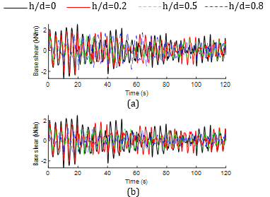
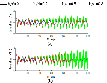
Figs. 6 and 7 depict the time history responses of base shear for both non-isolated and base-isolated tanks across different width ratios. In the non-isolated tank, the local and global peak values of the response are higher at w/L=0.1 compared to w/L=0.2. Conversely, for the slender baffle configuration (w/L=0.1 and h/d=0.8), the peaks are consistently higher, as seen in Fig. 6(a). On the other hand, in the base-isolated tank, the global peaks are consistently higher at h/d=0.5 regardless of the width ratios, as observed in Fig. 7. However, the local peaks at h/d=0.5 appear at varying time instances for different baffle widths, as evident from the figure.
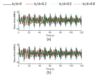
Whereas high frequency components are associated with the time history of base shear responses for the non-isolated tank in both initial and later stages of the responses, irrespective of the baffle configuration. Contrarily, low frequency responses are observed for the base-isolated responses, which is reasonably attributed to the implementation of nonlinear hysteretic bearing.
Moreover, Table 2 provides the global peak values. The base shear values for non-isolated tanks increase with higher h/d ratios, while for base-isolated tanks, the base shear values decrease, especially at w/L=0.1. This trend is also observed for non-isolated tanks at w/L=0.2. However, for base-isolated tanks, the base shear initially increases and then decreases notably. Overall, the use of hysteretic bearing has led to a reduction in base shear ranging from 2% to 48%, depending on the configurations. Overall, maximum reduction in base shear is observed in tank with w/L=0.1 and h/d=0.8 whereas minimal reduction is noticed in tank with w/L=0.1 and h/d=0.2.
Table 2 Absolute peak response of total base shear
|
w/L ratio |
h/d ratio |
Base shear (kN/m) |
Non-isolated |
Isolated |
|
0 |
0 |
4.43 |
2.57 |
|
0.1 |
0.2 |
4.11 |
3.87 |
|
0.5 |
4.41 |
3.65 |
|
|
0.8 |
5.37 |
2.98 |
|
|
0.2 |
0.2 |
4.02 |
3.57 |
|
0.5 |
4.07 |
3.98 |
|
|
0.8 |
4.79 |
2.52 |
|
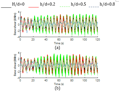
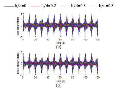
3.5. Effect on impulsive and convective base shear
Figs. 8 and 9 depict the time history responses of impulsive base shear for both non-isolated and base-isolated tanks at different width ratios. As can be seen from the Fig. 8, the changes in the dimension of the baffle have not much affected the time history impulsive base shear behavior. Whereas the convective parameter is significantly affected due to the change in width specifically at h/d=0.5 and w/L=0.2, as observed in Fig. 9. Furthermore, the time history pattern of impulsive base shear for the non-isolated tank almost follows a similar pattern with that of the total base shear, which indicates that the total base shear is noticeably influenced by its impulsive component. Since, convective component represents the sloshing portion of liquid, the resulting base shear due to this component gives a low frequency response throughout the time history behavior as compared to the impulsive one except for the aforementioned baffle configuration.
Figs. 10 and 11 depict the time history responses of convective base shear for both non-isolated and base-isolated tanks at different width ratios. As can be seen from the Fig. 10, the temporal behavior of the component for different width of the baffle in non-isolated tank is almost similar during the initial phase whereas a typical phase lag is observed during the later stage of the responses. However, for the isolated tank, the component is significantly biased due to the change in width specifically at h/d=0.5. Thus, it can be interpreted that the slender dimension of the baffle (i.e., w/L=0.1) is efficient in controlling the impulsive and convective components for the base-isolated tank under an irregular ground motion.
Furthermore, the implementation of nonlinear hysteretic bearing considerably altered the high-frequency components to the low-frequency components in both the impulsive and convective responses, as can be seen from the above figures. In addition, it is evident that the global peak and subsequent local peaks of impulsive responses are reduced in base-isolated tank-baffle configurations whereas a converse tendency is observed for the convective response. It can be demonstrated that more amount of liquid is participating in oscillation at the convective zone by virtue of base isolation. The peak values of the components are presented in Tables 3 and 4. It is noticed that the impulsive component is invariably reduced up to 55 percent due to the decoupling of tank base by hysteretic bearing for different baffle configurations. Conversely, the convective component has shown a significant increase for different configurations except at h/d=0.8 and in tank with no block. On the other hand, the impulsive responses are dominant over the convective ones for the non-isolated tank case whereas converse phenomenon is observed in majority of the configurations except at h/d=0.8 for both of the baffle widths considered.
Table 3 Absolute peak response of impulsive base shear
|
w/L ratio |
h/d ratio |
Impulsive base shear (kN/m) |
Non-isolated |
Isolated |
|
0 |
0 |
4.09 |
1.83 |
|
0.1 |
0.2 |
3.87 |
1.95 |
|
0.5 |
4.14 |
2.41 |
|
|
0.8 |
4.86 |
2.24 |
|
|
0.2 |
0.2 |
3.76 |
2.45 |
|
0.5 |
3.88 |
3.75 |
|
|
0.8 |
4.49 |
2.11 |
|
Table 4 Absolute peak response of convective base shear
|
w/L ratio |
h/d ratio |
Convective base shear (kN/m) |
Non-isolated |
Isolated |
|
0 |
0 |
2.70 |
2.34 |
|
0.1 |
0.2 |
2.21 |
2.88 |
|
0.5 |
1.43 |
3.37 |
|
|
0.8 |
1.86 |
1.63 |
|
|
0.2 |
0.2 |
2.13 |
3.47 |
|
0.5 |
1.40 |
4.79 |
|
|
0.8 |
1.31 |
1.22 |
|
Table 5 Absolute peak bearing displacement
|
w/L ratio |
h/d ratio |
xb (cm) |
|
0 |
0 |
2.57 |
|
0.1 |
0.2 |
2.51 |
|
0.5 |
2.82 |
|
|
0.8 |
2.68 |
|
|
0.2 |
0.2 |
2.49 |
|
0.5 |
2.93 |
|
|
0.8 |
2.54 |
Overall, maximum reduction in impulsive base shear is observed in tank without baffle whereas minimal reduction is noticed in tank with w/L=0.2 and h/d=0.5. Contrarily, the increase in convective base shear is maximum in tank with w/L=0.2 and h/d=0.5 and minimal at w/L=0.1 and h/d=0.8. Moreover, such contributions can be clearly extracted from Figs. 12 and 13, which illustrate the percentage contribution of impulsive and convective base shear for different configuration of the baffle.
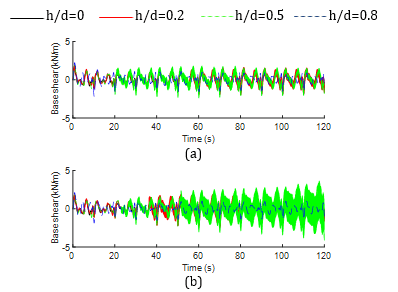
3.6. Effect on isolator displacement
Fig. 14 displays the time history responses of isolator displacement across different baffle configurations. The isolator displacement behavior is nearly identical for both width ratios, which indicates that the time history behavior is not much affected due to the change in width of the baffle. However, the height of the baffle has a noticeable impact in the temporal behavior, as observed. Maximum values are listed in Table 5 for various tank-baffle setups. Notably, the isolator experiences maximum deformation at h/d=0.5 regardless of the w/L ratios. Generally, an increase in the h/d ratio initially leads to higher isolator displacement, which then decreases over time.
(a)
(b)
3.7. Correlation among the critical dynamic responses
Figs. 15 and 16 display the correlation among the dynamic responses for non-isolated and base-isolated tanks for different baffle configurations. It can be seen that the total base shear and sloshing amplitude for the non-isolated tank follow almost identical trend of variation with respect to the baffle configurations. It demonstrates that higher sloshing amplitude imparts higher base shear response and vice versa. Moreover, for the base-isolated tank, the behaviour of total base shear, sloshing amplitude and isolator displacement is also nearly similar representing the in-phase mutual tendency of variation among these responses. It indicates that higher bearing displacement is accompanied by higher sloshing amplitude followed by higher base shear response and vice versa.
5. Conclusion
The study assesses the seismic responses of a base-isolated rectangular fluid tank with a bottom mounted vertical baffle by using a nonlinear hysteretic bearing isolator under a long duration irregular excitation. Galerkin's finite element method is employed to model the liquid domain. The present study leads to the following conclusions:
- The prime outcome of the study is that the seismic responses are efficiently controlled for the vertically baffled base-isolated tank even after the system is subjected to an irregular excitation. It indicates that the safety of fluid containers can be assured under such circumstances.
- The variation in sloshing amplitude and base shear components is notably influenced by changes in the h/d ratio, more so than changes in the w/L ratio.
- The implementation of base isolation decreases sloshing amplitudes by 12% to 34% across various baffle configurations, except when h/d=0.5.
- The total base shear in isolated tanks is decreased by 2% to 48% based on various baffle configurations.
- The impulsive responses are dominant over the convective ones for the non-isolated tank case whereas converse phenomenon is observed in majority of the configurations except at h/d=0.8 for both of the baffle widths considered.
- The implementation of nonlinear hysteretic bearing has considerably shifted the high-frequency components to the low-frequency components in both the impulsive and convective responses.
- The time history behavior is not much affected due to the change in width of the baffle whereas the height of the baffle has a noticeable impact.
- The isolator displacement consistently reaches its maximum when h/d=0.5, regardless of the baffle width. However, the difference of this maximum value with other configurations is considerably lower.
Acknowledgements
The authors would like to thank National Institute of Technology Rourkela for providing computational support.
References
[1] E. Brunesi, R. Nascimbene, M. Pagani and D. Beilic (2015). “Seismic performance of storage steel tanks during the May 2012 Emilia, Italy, earthquakes”. Journal of Performance of Constructed Facilities, 29(5), 04014137.
View Article
[2] S. Mitra and K. P. Sinhamahapatra (2007). “Slosh dynamics of liquid-filled containers with submerged components using pressure-based finite element method”. Journal of Sound and Vibration, 304(1–2), 361–381.
View Article
[3] S. K. Nayak and K. C. Biswal (2013). “Quantification of seismic response of partially filled rectangular liquid tank with submerged block”. Journal of Earthquake Engineering, 17(7), 1023–1062.
View Article
[4] X. Cheng, W. Jing and L. Gong (2019). “Liquid sloshing problem in a concrete rectangular LSS with a vertical baffle”. Arabian Journal for Science and Engineering, 44(5), 4245–4256.
View Article
[5] P. K. Panigrahy, U. K. Saha and D. Maity (2009). “Experimental studies on sloshing behavior due to horizontal movement of liquids in baffled tanks”. Ocean Engineering, 36(3–4), 213–222.
View Article
[6] M. A. Xue, J. Zheng, P. Lin and X. Yuan (2017). “Experimental study on vertical baffles of different configurations in suppressing sloshing pressure”. Ocean Eng. 136, 178–189.
View Article
[7] S. C. Jiang, W. Bai, J. J. Lan, (2022a). “Influence of a vertical baffle on suppressing sway motion response of a tank coupled with sloshing actions in waves”. Ocean Eng. 260, 111999.
View Article
[8] S. C. Jiang, A. Feng, B. Yan, (2022b). “Numerical simulations for internal baffle effect on suppressing sway-sloshing coupled motion response”. Ocean Eng. 250, 110513.
View Article
[9] V. Sriram, S. Sannasiraj and V. Sundar, (2006). “Numerical simulation of 2D sloshing waves due to horizontal and vertical random excitation”. Appl. Ocean Res. 28 (1), 19–32.
View Article
[10] M. Luo, C. Koh and W. Bai, (2016). “A three-dimensional particle method for violent sloshing under regular and irregular excitations”. Ocean Eng. 120, 52–63.
View Article
[11] Z. H. Wang, S. C. Jiang, W. Bai and J. X. Li, (2023). “Liquid sloshing in a baffled rectangular tank under irregular excitations”. Ocean Eng, 278, 114472.
View Article
[12] V. R. Panchal and R. S. Jangid (2011). “Seismic response of liquid storage steel tanks with variable frequency pendulum isolator”. KSCE J. Civ. Eng. 15 (6): 1041–1055.
View Article
[13] A. A. Seleemah and M. El-Sharkawy (2011). “Seismic response of base isolated liquid storage ground tanks”. Ain Shams Eng. J. 2 (1): 33–42.
View Article
[14] X. Cheng, W. Jing and L. Gong (2017). “Simplified model and energy dissipation characteristics of a rectangular liquid-storage structure controlled with sliding base isolation and displacement-limiting devices”. J. Perform. Constr. Facil. 31 (5): 04017071.
View Article
[15] M. K. Shrimali and R. S. Jangid (2002). “Seismic response of liquid storage tanks isolated by sliding bearings”. Engineering Structures, 24(7), 909–921.
View Article
[16] M. K. Shrimali and R. S. Jangid (2002). “A comparative study of performance of various isolation systems for liquid storage tanks”. International Journal of Structural Stability and Dynamics, 02(04), 573–591.
View Article
[17] M. K. Shrimali and R. S. Jangid (2004). “Seismic analysis of base-isolated liquid storage tanks”. Journal of Sound and Vibration, 275(1–2), 59–75.
View Article
[18] P. Pal (2012). “Slosh dynamics of liquid-filled rigid containers: two-dimensional meshless local Petrov-Galerkin approach”. Journal of engineering mechanics, 138(6), 567-581.
View Article
[1] E. Brunesi, R. Nascimbene, M. Pagani and D. Beilic (2015). “Seismic performance of storage steel tanks during the May 2012 Emilia, Italy, earthquakes”. Journal of Performance of Constructed Facilities, 29(5), 04014137. View Article
[2] S. Mitra and K. P. Sinhamahapatra (2007). “Slosh dynamics of liquid-filled containers with submerged components using pressure-based finite element method”. Journal of Sound and Vibration, 304(1–2), 361–381. View Article
[3] S. K. Nayak and K. C. Biswal (2013). “Quantification of seismic response of partially filled rectangular liquid tank with submerged block”. Journal of Earthquake Engineering, 17(7), 1023–1062. View Article
[4] X. Cheng, W. Jing and L. Gong (2019). “Liquid sloshing problem in a concrete rectangular LSS with a vertical baffle”. Arabian Journal for Science and Engineering, 44(5), 4245–4256. View Article
[5] P. K. Panigrahy, U. K. Saha and D. Maity (2009). “Experimental studies on sloshing behavior due to horizontal movement of liquids in baffled tanks”. Ocean Engineering, 36(3–4), 213–222. View Article
[6] M. A. Xue, J. Zheng, P. Lin and X. Yuan (2017). “Experimental study on vertical baffles of different configurations in suppressing sloshing pressure”. Ocean Eng. 136, 178–189. View Article
[7] S. C. Jiang, W. Bai, J. J. Lan, (2022a). “Influence of a vertical baffle on suppressing sway motion response of a tank coupled with sloshing actions in waves”. Ocean Eng. 260, 111999. View Article
[8] S. C. Jiang, A. Feng, B. Yan, (2022b). “Numerical simulations for internal baffle effect on suppressing sway-sloshing coupled motion response”. Ocean Eng. 250, 110513. View Article
[9] V. Sriram, S. Sannasiraj and V. Sundar, (2006). “Numerical simulation of 2D sloshing waves due to horizontal and vertical random excitation”. Appl. Ocean Res. 28 (1), 19–32. View Article
[10] M. Luo, C. Koh and W. Bai, (2016). “A three-dimensional particle method for violent sloshing under regular and irregular excitations”. Ocean Eng. 120, 52–63. View Article
[11] Z. H. Wang, S. C. Jiang, W. Bai and J. X. Li, (2023). “Liquid sloshing in a baffled rectangular tank under irregular excitations”. Ocean Eng, 278, 114472. View Article
[12] V. R. Panchal and R. S. Jangid (2011). “Seismic response of liquid storage steel tanks with variable frequency pendulum isolator”. KSCE J. Civ. Eng. 15 (6): 1041–1055. View Article
[13] A. A. Seleemah and M. El-Sharkawy (2011). “Seismic response of base isolated liquid storage ground tanks”. Ain Shams Eng. J. 2 (1): 33–42. View Article
[14] X. Cheng, W. Jing and L. Gong (2017). “Simplified model and energy dissipation characteristics of a rectangular liquid-storage structure controlled with sliding base isolation and displacement-limiting devices”. J. Perform. Constr. Facil. 31 (5): 04017071. View Article
[15] M. K. Shrimali and R. S. Jangid (2002). “Seismic response of liquid storage tanks isolated by sliding bearings”. Engineering Structures, 24(7), 909–921. View Article
[16] M. K. Shrimali and R. S. Jangid (2002). “A comparative study of performance of various isolation systems for liquid storage tanks”. International Journal of Structural Stability and Dynamics, 02(04), 573–591. View Article
[17] M. K. Shrimali and R. S. Jangid (2004). “Seismic analysis of base-isolated liquid storage tanks”. Journal of Sound and Vibration, 275(1–2), 59–75. View Article
[18] P. Pal (2012). “Slosh dynamics of liquid-filled rigid containers: two-dimensional meshless local Petrov-Galerkin approach”. Journal of engineering mechanics, 138(6), 567-581. View Article