International Journal of Civil Infrastructure (IJCI)
ISSN: 2563-8084

Volume 7 - Year 2024- Pages 43-49
DOI: 10.11159/ijci.2024.005
Sustainability in the Anthropocene: Evaluation of Glass Fiber Reinforced Polymer (GFRP) and Steel in Flexed Concrete Beams
Bolívar Maza1, Julio Silverio2, Daniela Maza3
1Universidad Técnica Particular de Loja
San Cayetano Alto, Loja, Ecuador
First. bhmaza@utpl.edu.ec
Second. jcsilverio@utpl.edu.ec
Third. dsmaza@utpl.edu.ec
Abstract - The corrosion of steel embedded in structural elements of ordinary Portland cement concrete (OPC) induces cracks and fissures, contributing to the reduction of the Useful Life Period of Structures (RULPS). The global OPC industry is the third-largest emitter of Anthropogenic CO2(A_CO2). Producing one ton of OPC implies producing another ton of CO2, accounting for a 7% carbon footprint on a global scale. The RULPS of Reinforced Concrete (RC) housing due to reinforcement corrosion doubles A_CO2 emissions. Glass Fiber Reinforced Polymer (GFRP) bars do not corrode. The objective is to contribute to reducing CO2 emissions in RC constructions. The behavior of GFRP and STEEL concrete reinforcement was studied separately through shear, flexion, and traction in concrete beams. Three specimens of simply reinforced concrete beams with steel (V1SRA, V2SRA, and V3SRA) were fabricated according to ASTM C-31, as well as a model of a simply reinforced beam with GFRP (V1SRP). Flexural tests using the three-point method were executed on a SHIMADZU machine. Numerical records were organized for statistical processing. It was found that the tensile strength of GFRP bars applied as reinforcement in concrete beams exceeds by 37.41% the tensile strength of reinforcing steel bars under the same conditions. It is reported that the beam model (VSRP, Af=cm2) does not show significant fissures before failure. It is concluded that the toughness of polymer bars reinforced with glass fibers significantly attenuates the generation of fissures and cracks in concrete beams. In this sense, the useful life of concrete structures is stabilized. The two materials studied must coexist as a philosophy of sustainable design.
Keywords: Finite elements; Corrosion; Emissions; Shear stress; Useful life period.
© Copyright 2024 Authors - This is an Open Access article published under the Creative Commons Attribution License terms. Unrestricted use, distribution, and reproduction in any medium are permitted, provided the original work is properly cited.
Date Received: 2024-02-09
Date Revised: 2024-05-17
Date Accepted: 2024-05-27
Date Published: 2024-06-12
1. Introduction
Steel embedded in concrete is prone to corrosion, particularly in aggressive environments, leading to deterioration and a reduction in the Useful Life Period of Structures (RULPS)[1]. The rate of corrosion of the steel reinforcement in concrete is a function of environmental characteristics, humidity, oxygen, and temperature [2]. Corrosion products accumulate around the reinforcement with a volume six times greater, creating internal stress states and detachment of the covering concrete. The useful life period of structures (ULPS) is threatened by cracking, fatigue, corrosion, and fissures [3]. Creating protection for embedded reinforcement in concrete to prevent the entry of depassivating substances on the reinforcement is related to the quality of the concrete and the depth of the covering [4]. The depassivation of steel reinforcement embedded in concrete due to chloride ion penetration is the primary vector for the destruction of CR structural assets over time [5]. Economic values are highlighted due to corrosive pathology up to 3% of the Gross Domestic Product (GDP). Global pathological corrosive occurrence rates range from 14% to 64%, reflecting the reductive problem of the structural life of construction assets [6]. The accelerated global industrialization of urbanization increases Greenhouse Gas (GHG) emissions [7]. China expects an urbanization rate of 70% by 2030 and is looking at non-traditional materials like Cross-Laminated Timber, which will reduce carbon emissions by 40% [7]. Co2 emissions are linked to the construction, operational, and deconstructive stages.
The high tensile strength of GFRPs and their ability to resist corrosion allow for the reconstruction of CR structural assets affected by corrosion to stabilize the ULPS and adapt to the increases in load resisted by the structure [8]. Clearly, the construction of structures reinforced with GFRP is sustainable. In this sense, if the corrosion of steel reinforcement in concrete contributes to RULPS, can GFRPs replace steel bars to reinforce concrete? This work investigates the behavior of GFRP and STEEL as reinforcements in concrete beams subjected to flexion, considering sustainability. The main objective is to contribute to reducing CO2 emissions in the construction sector, comparing the resistant response to tractional and gravitational stresses of GFRP and STEEL in reinforcement states in concrete beams.
2. Materials
Fiber is any natural or synthetic object in the form of fine yarn of mineral or organic origin [9]. According to [10] there are three predominant types of fibers: glass fiber, material resulting from the melting of glass, flows through a piece of very fine holes that when solidified has sufficient flexibility, aramid fiber, of organic and synthetic origin that has high strength and modulus of elasticity due to a perfect alignment of polymers, carbon fiber 10 times more resistant to traction than steel and much lighter.
Adhesion acts as a bonding agent, its mission is to transmit stresses from one fiber to another and to protect against possible mechanical and environmental damage [9]. [11] reports that GFRP bars as concrete reinforcement contribute to increase the durability of structures exposed to corrosion phenomena. [12] states that S-type GFRP has better strength and stiffness performance and better deformation behaviour compared to E-type GFRP. GFRP in the form of corrugated rods are recommended for the reinforcement of concrete exposed to aggressive environments of temperature, chemical and mechanical order [11]. In this research, S-type Glass Fiber Reinforced Polymer Reinforced Polymer (GFRP) corrugated rods are used as reinforcement for concrete. Table 1 shows the properties of the described fibers that are part of the fiber-reinforced polymer composition [13].
In this research, corrugated steel bars grade 60 are used, with a yield strength of 420 MPa, and a carbon alloy in the range of 0.30% to 0.33% according to the standard NTE INEN 2 167:2014 [14]. The bars have a diameter (∅) of 12.7 mm. The differences between steel bars and GFRP bars according to ACI 440.1R-15 [15] are: GFRPs subjected to tension exhibit linear elastic failure unlike steel bars which transition to a plastic state until failure. GFRPs are anisotropic while steel is isotropic, and GFRP bars have a lower creep-rupture threshold compared to steel. The coefficient of thermal expansion is different in longitudinal and transverse directions. The fire resistance duration is shorter than that of steel. In case of degradation of GFRP bars, the degradation mechanism is benign to the surrounding concrete, unlike steel where corrosion products induce stress leading to the failure of the member. The guide for the design and construction of externally bonded FRP systems to strengthen concrete structures ACI 440.2R-08 [16] shows the physical and mechanical properties of FRPs. Table 1 present physical, mechanical, and behavioral properties of STEEL and GFRP bars in twelve significant parameters. [16].
Table 1. Physical, Mechanical, and Behavioral Properties of STEEL and GFRP Bars
|
PARAMETER |
STEEL |
GFRP |
|
Density (Kg/m3) |
7800 |
1600 |
|
Weight (g) |
1200 |
400 |
|
Volume Fiber Content |
99% |
70% de fiber |
|
Tensile Strength (MPa) |
420 |
1300 |
|
Elastic Modulus (GPa) |
200 |
50 |
|
Minimum Yield Limit (MPa) |
420 |
- |
|
Maximum Yield Limit (MPa) |
540 |
- |
|
Elongation (%) |
14 |
1.2 |
|
Unit Strain (%) |
25 |
2.2 |
|
Corrosion Resistance |
Corrosive |
No corrosive |
|
Electrical Conductivity |
Conductor |
No conductor |
|
Electrical Conductivity |
Conductor |
No conductor |
Note: [14]; [17]
- The density ratio (7800 Kg)/(1600 m3 )=4.88 indicates that GFRPs are five times lighter than steel, a significant indicator for reducing mass in a structure.
- GFRP bars exhibit linear elastic behavior until failure under tensile stresses, unlike steel bars which have elastoplastic behavior. GFRP bars are 210% more resistant to tension than steel bars.
- The anti-corrosive property of GFRP bars embedded in concrete allows for the fulfillment of the structure's useful life period.
3. Metodology
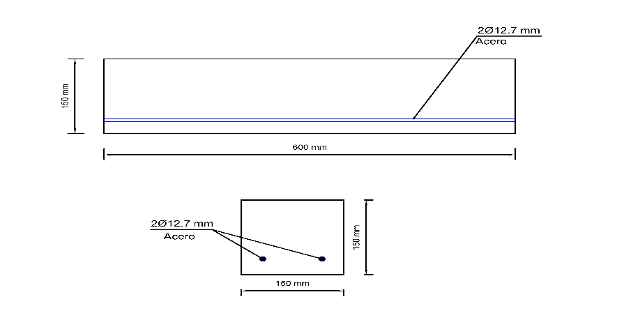
To evaluate the flexural behavior of steel and GFRP reinforcements, three simply supported reinforced concrete beams (SSRCB) with steel area A_s = 2.50 cm² and one simply supported concrete beam reinforced with GFRP (SRCBW_GFRP) with A_GFRP = 1.57 cm² are constructed. The concrete strength for both models is f'c = 24 MPa. The dimensions are in accordance with ASTM-C39/C39M-19 and ASTM – C31. The three-point method is used, with controlled load and speed on the Zhimadzu machine in the Material Resistance Laboratory (MRL) at the Technical University of Loja (UTPL). The analysis of the results is obtained according to the ACI 318-19 code. The flexural study of beams reinforced with GFRP bars is in line with the ACI committee 440.1R-06. Rectangular sections are considered with a layer of GFRP and STEEL reinforcement respectively.
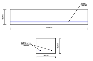
The behavior of GFRP bars in the tensile test is linear elastic up to rupture, understanding that the constitutive equation of this material responds to Hooke's law throughout the range of deformations: f_f = E_f.ε_f. The maximum deformation of the concrete is 0.003. To evaluate the resistance to flexural stresses, beam-type specimens are designed and constructed. Figure 1 shows the resistant profile of a simply reinforced concrete beam with GFRP.
To ensure the comparison of physical test results, two numerical models of virtual beams are generated according to the V2SRA (As = 157.08 mm²) and V3SRP (Af = 157.08 mm²) models, in accordance with ASTM-C39/C39M-19 and ASTM – C31 standards. The modeling is carried out in open-access software using the Finite Element Method (FEM). The results of the numerical modeling are analyzed using the Finite Element Analysis (FEA) method
4. Results and Discussion
In this study, the flexural test was conducted in accordance with the requirements of the NTE INEN 2554 [18] and ASTM C 293 [19] standards. Table 2 shows specific values of the beam specimens subjected to real laboratory tests.
Table 2. Presents beam models with their reinforcements and specific dimensions
|
Type of Beams |
Model |
DIMENSIONS |
Weight (Kg) |
||
|
Base (mm) |
Height (mm) |
Length (mm) |
|||
|
Simply reinforced with Steel |
VISRA |
150 |
152 |
597 |
32.89 |
|
V2SRA |
150 |
153 |
596 |
32.81 |
|
|
V3SRA |
150 |
152 |
597 |
32.48 |
|
|
Simply reinforced with GFRP |
V1SRP |
151 |
152 |
598 |
31.61 |
The models V1SRA, V2SRA, and V3SRA have 2.53 cm² of steel reinforcement. In contrast, the V1SRP model has reinforcement of 1.57 cm² (GFRP bars with ϕ = 10 mm are available).
The properties of the materials that make up the concrete beams are designated based on the results obtained theoretically and experimentally. For the concrete, its density, plasticity, and behavior under tension and compression are considered. For the steel and GFRP bars, their density, yield, and rupture are designated. The elastoplastic behavior of the steel bars and the linear elastic behavior of the GFRP bars up to their failure were taken into account. The materials created with their respective properties are assembled so that the reinforced concrete structure with simply reinforced beams with corrugated steel bars and GFRP operates as a single element. In addition, the reinforcement area was defined, taking into account the following: Longitudinal reinforcement with GFRP bars for simply reinforced beams (Ø 10 mm), Longitudinal reinforcement with steel bars for simply reinforced beams (Ø 12.7 mm), concrete quality for both models f'c=24 MPa. Support conditions and the position, magnitude, and direction of the loads acting on the beam are established, following ASTM C293. Results are obtained from deformations, maximum loads applied at the center of the span, crack layout, and deformations. Table 3 contains results from the different tests and models.
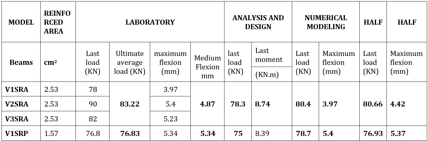
Note: The most outstanding results from the numerical analysis, flexural test results in the laboratory, and the modeling results in open-source software are presented. The Finite Element Method (FEM) is used.
- The models V1SRA, V2SRA, and V3SRA are reinforced with steel (ø 12.7 mm, A_s = 2.53 cm²). The V1SRP model is reinforced with GFRP (ø 10 mm, A_GFRP = 1.57 cm²).
- The steel-reinforced concrete beam model apparently resists a higher load than the GFRP-reinforced concrete beam model by an average of 4.85%. Also evident is the superiority of A_s = 2.53 cm² > A_GFRP = 1.57 cm² by 60%.
- The 60% percentage is an indicator that gives greater joint resistance (tension + compression) to the VSRP beam model (A_GFRP = 1.57 cm²) by 37.41%. The superiority of resistance to gravitational load of GFRP over STEEL is demonstrated.
- The similarity of the results indicates a positive correlation of the variables studied in this research.
Figure 3 shows stress-strain curves based on tests in the MRL
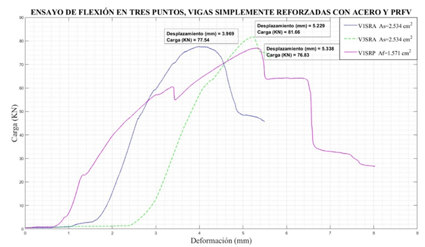
Note: Figure 3 shows the results described in Table 3.
- The irregular deformation of the V1SRP curve at deformations (1.3 and 3.39) mm is closely related to the adherence between the polymer and concrete.
- For the fracture points of the blue and magenta curves (V1SRA and V1SRP, respectively), the amount of energy expended is evidently greater for GFRP, indicating greater toughness and flexibility of GFRP compared to steel when both materials are subjected to gravitational loads inducing tensile stresses in the reinforcement.
The analysis of Figure 3 indicates that the polymer beam (VSRP) shows the highest tension among the beams analyzed, suggesting high resistance to compression and flexion relative to its reinforcement area. This implies that the polymer material, despite having a smaller reinforcement area, can withstand considerable loads relative to its size. Among the steel beams, Steel Beam 2 shows the highest tension, followed by Steel Beam 3 and Steel Beam 1. This suggests that Steel Beam 2 could be the most efficient in terms of strength relative to the reinforcement area. The exceptionally high tension of the polymer beam, despite having a smaller reinforcement area than the steel beams, indicates high material efficiency. This suggests that the polymer is capable of supporting considerable loads relative to its size, which could be advantageous in applications where space, weight, or corrosive environment are critical factors. The reduction in adhesive strength has been observed between 33% and 50% in many research programs [20]; [21]; [9]. It is known that pull-out tests are largely performed as a comparative test, as those resistances do not represent the true adhesive forces in flexural sections [22].
It is known that GFRP bars are four times lighter than steel. GFRP bars are recommended for reinforcing concrete exposed to aggressive environments, temperature, and chemical and mechanical orders [11]. Note that the green curve (GFRP) elastically deforms until reaching the ultimate resistance point (78.72 KN), exceeding steel fracture by 21.43 KN. After reaching the ultimate resistance point, it is assured that GFRPs fail suddenly after a period known as the resistance time. This phenomenon is known as creep rupture or static fatigue [23]. The design of concrete elements reinforced with GFRP bars is analogous to the design of reinforced concrete elements with steel bars. Bending can be calculated based on assumptions similar to those made for members reinforced with steel bars[15] . Table 4 presents bending results expressed in nominal moments and ultimate resistance.
Table 4. Presents Fundamental Data Used in Design Modeling for Beam Flexion
|
Reinforcement |
Diameter |
Reinforcement area |
Elastic modulus |
Concrete |
Mn |
Mu |
|
|
mm |
mm2 |
MPa |
MPa |
KN.m |
KN.m |
|
VSRA |
12.7 |
253 |
200 |
24 |
10.78 |
9.16 |
|
VSRA |
10 |
157.08 |
200 |
24 |
7 206 |
6 125 |
|
VSRP |
10 |
157.08 |
50 |
24 |
15.23 |
9.9 |
Note: A summary of flexural design results for resistant sections of beams described in Table 4 is presented.
- The V1SRA model (As = 253 mm²) resists Mn = 10.78 KN.m (flexion). Comparing with V3SRP (Af = 157.08 mm²), which contributes Mn = 15.23 KN.m (flexion), it is 41.28% stronger despite having a smaller area of longitudinal reinforcement (60%).
- The same reflection for Mu (Ultimate Resistant Moment) is 8.8% higher than the V1SRA model. A reduction factor of 0.65 is considered due to concrete crushing effects.
- The comparative scheme for equal reinforcement conditions as expressed in V2SRA (As = 157.08 mm²), Mn = 7.206 KN.m (flexion), and V3SRP (Af = 157.08 mm²) with Mn = 15.23 KN.m, shows a superiority of 111%. For Mu, the V3SRP model has more resistance (61%) compared to V2SRA.
[11] argued that GFRP bars as concrete reinforcement contribute to increasing the durability of structures exposed to the phenomenon of corrosion. [12] reports that Type S GFRP shows better performance in terms of resistance and stiffness and better behavior in deformations compared to Type E.
When evaluating the resistance to tensile stress in GFRP and STEEL in conditions of concrete beam reinforcement and subjected to bending loads in the laboratory, GFRP bars show superiority in resistance to tensile stress (37.41%).
Standards NTE INEN 2167 [24], [17] state that GFRP does not corrode, is not an electrical conductor, and is null as a thermal conductor. In this context, the use of GFRP as reinforcement for concrete structural elements contributes to stabilizing the structure's useful life period. Conversely, steel reinforcement in concrete easily corrodes when depassivated by humidity or aggressive substances that enter through cracks and fissures in the concrete, triggering the reduction of the operational life period [4], [6], [7], [25]–[28].
Results from Table 4 for flexural design of concrete beam models (V1SRA, V2SRA, V3SRP) show that Mu = 9.9 KN.m for the V3VSRP model and for the V2SRA model Mu = 6.13 KN.m. The ultimate resistant bending effort for GFRP is 61.92% higher compared to STEEL. These results are undeniable along with other advantages of GFRP such as no corrosion, lighter than steel, electromagnetic neutrality. In this sense, the use of GFRP to reinforce concrete structural elements contributes to reducing the negative impact on concrete due to corrosion of the reinforcement. GFRP material helps reduce maintenance costs and contributes to stabilizing the ULPS. In the same sense, ensuring ULPS stability means reducing CO₂ emissions. For [29] GFRP can replace steel reinforcement rods in concrete. For [30] a greater depth should be considered compared to RC, especially in flexion. In this research, resistance was penalized using the factor 0.65.
5. Conclusion
Comparing the tensile strength between reinforcements embedded in concrete beams (STEEL and GFRP), the superior tractive effort supported by GFRP is undeniable (37.41% more than steel), even considering a resistance penalization factor of φ = 0.65 when not considering greater depths in flexion.
For equal reinforcement area conditions (STEEL and GFRP) in concrete beams, the ultimate resistant moment (M_u) for the GFRP model (V3SRP) exceeds by 61% that of the STEEL model (V2SRA), also considering a penalization factor φ = 0.65, which can be avoided by increasing the quality of concrete.
The reduction in ductile failure of the model (V3SRP) is directly linked to the lower value of the elastic modulus of GFRP compared to STEEL, where design by Service Limit State should be considered.
GFRP, being more resistant in tensile effort, intrinsically contributes to reducing concrete cracks, thereby stabilizing the useful life period of the concrete structure and reducing CO2 emissions.
The toughness of GFRP bars embedded in concrete beams under tensile stresses significantly attenuates the generation of cracks and fissures, contributing to stabilizing the ULPS.
It would be advisable to carry out additional tests, such as fatigue tests and long-term durability analysis, to better understand how these materials behave under different conditions and over time.
GFRP can replace steel bars for certain concrete structures. In this sense, the two materials complement each other and coexist as a sustainable design philosophy in times of the Anthropocene.
References
[1] P. Valles Pla, "Estudio comparativo entre barras corrugadas de acero y de basalto para su uso en edificación," Universitat Politècnica de València, 2014.
[2] E. G. Segovia, G. de Vera, M. Miró, J. Ramis, and M. A. Climent, "Cement mortar cracking under accelerated steel corrosion test: A mechanical and electrochemical model," J. Electroanal. Chem., vol. 896, p. 115222, Sep. 2021, doi: 10.1016/J.JELECHEM.2021.115222.
View Article
[3] M. Abbas and M. Shafiee, "An overview of maintenance management strategies for corroded steel structures in extreme marine environments," Mar. Struct., vol. 71, p. 102718, May 2020, doi: 10.1016/J.MARSTRUC.2020.102718.
View Article
[4] S. Rath, P. Sancharoen, P. Klomjit, and S. Tangtermsirikul, "Effects of Carbonation on Corrosion Rate of Reinforcing Steel in Different Concrete and Repair Materials," Eng. J., vol. 25, no. 6, pp. 75-86, Jun. 2021, doi: 10.4186/ej.2021.25.6.75.
View Article
[5] B. Ge and S. Kim, "Probabilistic service life prediction updating with inspection information for RC structures subjected to coupled corrosion and fatigue," Eng. Struct., vol. 238, p. 112260, Jul. 2021, doi: 10.1016/J.ENGSTRUCT.2021.112260.
View Article
[6] X. Zhu, G. Zi, W. Lee, S. Kim, and J. Kong, "Probabilistic analysis of reinforcement corrosion due to the combined action of carbonation and chloride ingress in concrete," Constr. Build. Mater., vol. 124, pp. 667-680, Oct. 2016, doi: 10.1016/J.CONBUILDMAT.2016.07.120.
View Article
[7] Z. Duan, "Impact of climate change on the life cycle greenhouse gas emissions of cross-laminated timber and reinforced concrete buildings in China," J. Clean. Prod., vol. 395, p. 136446, Apr. 2023, doi: 10.1016/J.JCLEPRO.2023.136446.
View Article
[8] H. GÖKÇE, O. Ş.-G. U. J. of Science, and undefined 2021, "Aggressive Environment Performance of Low Energy Cements Containing Fly Ash," dergipark.org.trHS GÖKÇE, O ŞİMŞEKGazi Univ. J. Sci. 2021•dergipark.org.tr, doi: 10.35378/gujs.731497.
View Article
[9] J. L. Faria, I. del C. Díaz Pérez, and H. Wainshtok Rivas, "Estructuras de hormigón armado con barras de Polímero Reforzado con Fibras de Vidrio (PRFV)," Rev. Arquit. e Ing., vol. 11-3, pp. 1-16, 2017.
View Article
[10] J. W. Cevallos Cabrera and J. R. Toapanta Caisa, "Análisis de las curvas de desempeño de una viga reforzada con fibras de carbono y fibras de vidrio," Universidad Técnica de Ambato, 2016.
[11] E. de J. Vidaud Quintana and I. N. Vidaud Quintana, "Polimeros fibroreforzados, una alternativa sustentable frente al ataque de la corrosión en el concreto armado," Construcción y Tecnología en Concreto. pp. 32-35, 2014.
[12] J. Vegara Torres, "Estudio comparativo de barras corrugadas de diferentes materiales para armar hormigón," Universitat Politécnica de Valencia, 2019.
[13] R. Castillo Barahona, "Uso de polímeros reforzados con fibras (FRP) como refuerzo externo de elementos de concreto de puentes en Costa Rica," PITRA, vol. 1-6, p. 5, 2010.
[14] MIDUVI (Ministerio de Desarrollo Urbano y Vivienda), Estructuras de Hormigón Armado-NEC - SE - HM. Ecuador, 2014, p. 113.
[15] ACI (American Concrete Institute), 440.1R-15 Guide for the Design and Construction of Structural Concrete Reinforced with Fiber-Reinforced Polymer Bars. 2015, p. 88.
[16] ACI (American Concrete Institute), 440.2R-08 Guide for the Design and Construction of Externally Bonded FRP Systems for Strengthening Concrete Structures. 2008, p. 76.
[17] Armastek, "Armastek Ecuador." https://armastek-ec.com (accessed Feb. 02, 2024).
[18] INEN (Instituto Ecuatoriano de Normalización ), NTE INEN 2554: Hormigón de cemento hidráulico. Determinación de la resistencia a la flexión del hormigón. (Utilizando una viga simple con carga en los tercios). 2011, p. 300.
[19] ASTM, ASTM Designación: C 293 - 02 Standard Test Method for Flexural Strength of Concrete (Using Simple Beam With Center-Point Loading). 2016, p. 4.
[20] R. Espinoza Rojas, "REFUERZO ESTRUCTURAL CON POLÍMEROS REFORZADOS CON FIBRAS (PRF)," 2017, Accessed: Nov. 09, 2023. [Online]. Available:
View Article
[21] R. Aguiar, L. García, M. Zevallos, J. Palacios, and E. Menéndez, "SEISMIC REINFORCEMENT OF BUILDING BANCO CENTRAL DE MANTA REFORZAMIENTO SÍSMICO DE EDIFICIO BANCO CENTRAL DE MANTA RESUMEN," 2017.
[22] ACI (American Concrete Institute), 440.3R-12 Guide Test Methods for Fiber Reinforced Polymer (FRP) Composites for Reinforcing or Strengthening Concrete and Masonry Structures. 2012, p. 27.
[23] A. Rimkus, J. A. . Barros, V. Gribniak, and M. Rezazadeh, "Mechanical behavior of concrete prisms reinforced with steel and GFRP bar systems," Compos. Struct., vol. 220, pp. 273-288., 2019, doi: 10.1016/j.compstruct.2019.03.088.
View Article
[24] INEN (Instituto Ecuatoriano de Normalización), NTE INEN 2167: Varillas de acero con resaltes, laminadas en caliente, soldables, microaleadas o termotratadas, para hormigón armado. Ecuador, 2015.
[25] R. Corral H, S. Arredondo R, J. Almaral S, and J. Gómez S, "Corrosión por cloruros del acero de refuerzo embebido en concreto con agregado grueso reciclado y materiales cementantes suplementarios," Rev. Ing. construcción, vol. 28, no. 1, pp. 21-35, 2013, doi: 10.4067/S0718-50732013000100002.
View Article
[26] L. R. Flores-Quispe, "Gestión del talento humano y rentabilidad del sector hotelero de la región de Puno," Rev. Esc. Adm. Negocios, no. 87, pp. 59-77, Dec. 2019, doi: 10.21158/01208160.n87.2019.2410.
View Article
[27] C. G. Nogueira, L. Yoshio, and E. Zacchei, "Deterministic and probabilistic approaches for corrosion in RC structures: A direct proposed model to total service life predictions," Case Stud. Constr. Mater., vol. 18, pp. 1-20, Jul. 2023, doi: 10.1016/J.CSCM.2023.E01913.
View Article
[28] D. Peña, J. Rodriguez, D. Salcedo, and M. Suarez Pereira, "ESTIMACIÓN DE DAÑOS OCASIONADOS POR LA CARBONATACIÓN EN ESTRUCTURAS DE CONCRETO ARMADO EN LA CIUDAD DE NIRGUA," Gac. Técnica, vol. 23, no. 2, pp. 88-106, Jul. 2022, doi: 10.51372/GACETATECNICA232.7.
View Article
[29] O. Reyes Viñas, J. O. Martínez Cid, I. del C. Díaz Pérez, and A. Ramos Castillo, "Modelación, análisis y diseño de una losa de hormigón armado con forma atípica empleando como variantes: acero convencional y polímeros reforzados con fibras de vidrio.," Rev. Arquit. e Ing., vol. 15, no. 1, 2021, [Online]. Available:
View Article
[30] J. Hernández C, H. Wainshtok, and P. I. D. Díaz, "Diseño estructural." 2017.
[1] P. Valles Pla, "Estudio comparativo entre barras corrugadas de acero y de basalto para su uso en edificación," Universitat Politècnica de València, 2014.
[2] E. G. Segovia, G. de Vera, M. Miró, J. Ramis, and M. A. Climent, "Cement mortar cracking under accelerated steel corrosion test: A mechanical and electrochemical model," J. Electroanal. Chem., vol. 896, p. 115222, Sep. 2021, doi: 10.1016/J.JELECHEM.2021.115222. View Article
[3] M. Abbas and M. Shafiee, "An overview of maintenance management strategies for corroded steel structures in extreme marine environments," Mar. Struct., vol. 71, p. 102718, May 2020, doi: 10.1016/J.MARSTRUC.2020.102718. View Article
[4] S. Rath, P. Sancharoen, P. Klomjit, and S. Tangtermsirikul, "Effects of Carbonation on Corrosion Rate of Reinforcing Steel in Different Concrete and Repair Materials," Eng. J., vol. 25, no. 6, pp. 75-86, Jun. 2021, doi: 10.4186/ej.2021.25.6.75. View Article
[5] B. Ge and S. Kim, "Probabilistic service life prediction updating with inspection information for RC structures subjected to coupled corrosion and fatigue," Eng. Struct., vol. 238, p. 112260, Jul. 2021, doi: 10.1016/J.ENGSTRUCT.2021.112260. View Article
[6] X. Zhu, G. Zi, W. Lee, S. Kim, and J. Kong, "Probabilistic analysis of reinforcement corrosion due to the combined action of carbonation and chloride ingress in concrete," Constr. Build. Mater., vol. 124, pp. 667-680, Oct. 2016, doi: 10.1016/J.CONBUILDMAT.2016.07.120. View Article
[7] Z. Duan, "Impact of climate change on the life cycle greenhouse gas emissions of cross-laminated timber and reinforced concrete buildings in China," J. Clean. Prod., vol. 395, p. 136446, Apr. 2023, doi: 10.1016/J.JCLEPRO.2023.136446. View Article
[8] H. GÖKÇE, O. Ş.-G. U. J. of Science, and undefined 2021, "Aggressive Environment Performance of Low Energy Cements Containing Fly Ash," dergipark.org.trHS GÖKÇE, O ŞİMŞEKGazi Univ. J. Sci. 2021•dergipark.org.tr, doi: 10.35378/gujs.731497. View Article
[9] J. L. Faria, I. del C. Díaz Pérez, and H. Wainshtok Rivas, "Estructuras de hormigón armado con barras de Polímero Reforzado con Fibras de Vidrio (PRFV)," Rev. Arquit. e Ing., vol. 11-3, pp. 1-16, 2017. View Article
[10] J. W. Cevallos Cabrera and J. R. Toapanta Caisa, "Análisis de las curvas de desempeño de una viga reforzada con fibras de carbono y fibras de vidrio," Universidad Técnica de Ambato, 2016.
[11] E. de J. Vidaud Quintana and I. N. Vidaud Quintana, "Polimeros fibroreforzados, una alternativa sustentable frente al ataque de la corrosión en el concreto armado," Construcción y Tecnología en Concreto. pp. 32-35, 2014.
[12] J. Vegara Torres, "Estudio comparativo de barras corrugadas de diferentes materiales para armar hormigón," Universitat Politécnica de Valencia, 2019.
[13] R. Castillo Barahona, "Uso de polímeros reforzados con fibras (FRP) como refuerzo externo de elementos de concreto de puentes en Costa Rica," PITRA, vol. 1-6, p. 5, 2010.
[14] MIDUVI (Ministerio de Desarrollo Urbano y Vivienda), Estructuras de Hormigón Armado-NEC - SE - HM. Ecuador, 2014, p. 113.
[15] ACI (American Concrete Institute), 440.1R-15 Guide for the Design and Construction of Structural Concrete Reinforced with Fiber-Reinforced Polymer Bars. 2015, p. 88.
[16] ACI (American Concrete Institute), 440.2R-08 Guide for the Design and Construction of Externally Bonded FRP Systems for Strengthening Concrete Structures. 2008, p. 76.
[17] Armastek, "Armastek Ecuador." https://armastek-ec.com (accessed Feb. 02, 2024).
[18] INEN (Instituto Ecuatoriano de Normalización ), NTE INEN 2554: Hormigón de cemento hidráulico. Determinación de la resistencia a la flexión del hormigón. (Utilizando una viga simple con carga en los tercios). 2011, p. 300.
[19] ASTM, ASTM Designación: C 293 - 02 Standard Test Method for Flexural Strength of Concrete (Using Simple Beam With Center-Point Loading). 2016, p. 4.
[20] R. Espinoza Rojas, "REFUERZO ESTRUCTURAL CON POLÍMEROS REFORZADOS CON FIBRAS (PRF)," 2017, Accessed: Nov. 09, 2023. [Online]. Available: View Article
[21] R. Aguiar, L. García, M. Zevallos, J. Palacios, and E. Menéndez, "SEISMIC REINFORCEMENT OF BUILDING BANCO CENTRAL DE MANTA REFORZAMIENTO SÍSMICO DE EDIFICIO BANCO CENTRAL DE MANTA RESUMEN," 2017.
[22] ACI (American Concrete Institute), 440.3R-12 Guide Test Methods for Fiber Reinforced Polymer (FRP) Composites for Reinforcing or Strengthening Concrete and Masonry Structures. 2012, p. 27.
[23] A. Rimkus, J. A. . Barros, V. Gribniak, and M. Rezazadeh, "Mechanical behavior of concrete prisms reinforced with steel and GFRP bar systems," Compos. Struct., vol. 220, pp. 273-288., 2019, doi: 10.1016/j.compstruct.2019.03.088. View Article
[24] INEN (Instituto Ecuatoriano de Normalización), NTE INEN 2167: Varillas de acero con resaltes, laminadas en caliente, soldables, microaleadas o termotratadas, para hormigón armado. Ecuador, 2015.
[25] R. Corral H, S. Arredondo R, J. Almaral S, and J. Gómez S, "Corrosión por cloruros del acero de refuerzo embebido en concreto con agregado grueso reciclado y materiales cementantes suplementarios," Rev. Ing. construcción, vol. 28, no. 1, pp. 21-35, 2013, doi: 10.4067/S0718-50732013000100002. View Article
[26] L. R. Flores-Quispe, "Gestión del talento humano y rentabilidad del sector hotelero de la región de Puno," Rev. Esc. Adm. Negocios, no. 87, pp. 59-77, Dec. 2019, doi: 10.21158/01208160.n87.2019.2410. View Article
[27] C. G. Nogueira, L. Yoshio, and E. Zacchei, "Deterministic and probabilistic approaches for corrosion in RC structures: A direct proposed model to total service life predictions," Case Stud. Constr. Mater., vol. 18, pp. 1-20, Jul. 2023, doi: 10.1016/J.CSCM.2023.E01913. View Article
[28] D. Peña, J. Rodriguez, D. Salcedo, and M. Suarez Pereira, "ESTIMACIÓN DE DAÑOS OCASIONADOS POR LA CARBONATACIÓN EN ESTRUCTURAS DE CONCRETO ARMADO EN LA CIUDAD DE NIRGUA," Gac. Técnica, vol. 23, no. 2, pp. 88-106, Jul. 2022, doi: 10.51372/GACETATECNICA232.7. View Article
[29] O. Reyes Viñas, J. O. Martínez Cid, I. del C. Díaz Pérez, and A. Ramos Castillo, "Modelación, análisis y diseño de una losa de hormigón armado con forma atípica empleando como variantes: acero convencional y polímeros reforzados con fibras de vidrio.," Rev. Arquit. e Ing., vol. 15, no. 1, 2021, [Online]. Available: View Article
[30] J. Hernández C, H. Wainshtok, and P. I. D. Díaz, "Diseño estructural." 2017.