International Journal of Civil Infrastructure (IJCI)
ISSN: 2563-8084

Volume 7 - Year 2024- Pages 182-193
DOI: 10.11159/ijci.2024.019
Calculating Rainfall Flow into an Oil-Water Separator
Varvara Roubtsova1, Mathieu Emond-Castonguay2, Nathalie Thibeault 3
1Institut de recherche d’Hydro-Québec (IREQ)
1800, boul. Lionel-Boulet, Varennes, Canada
roubtsova.varvara@ireq.ca;
2,3Hydro-Québec
855, rue Sainte-Catherine Est, Montréal, Canada
emond-castonguay.mathieu@ hydroquebec.com
thibeault.nathalie@hydroquebec.com
Abstract - This paper describes a methodology for estimating rainfall discharge to an oil-water separator. The methodology is part of a comprehensive program for substation maintenance analysis developed by Hydro-Quebec. One purpose of hydraulic systems in substations is to collect rainwater with residual oil through a series of different types of oil collection pits connected to a system of conduits in turn connected to an oil-water separator. The oil collection pits and the separator are designed to protect the environment from oil spills or leaks. The methodology developed determines discharge from the pits through outlets of various design using a method of explicit time integration of analytical and empirical equations. One-dimensional Saint-Venant equations were solved by successive approximation using the under-relaxation method to model flow in the conduit network. A fictitious substation is used as an example and the accuracy of the results is analyzed and confirmed.
Keywords: rainfall flow, oil collection pit, pit outlet, conduit network
© Copyright 2024 Authors - This is an Open Access article published under the Creative Commons Attribution License terms. Unrestricted use, distribution, and reproduction in any medium are permitted, provided the original work is properly cited.
Date Received: 2024-01-11
Date Revised: 2024-07-24
Date Accepted: 2024-07-30
Date Published: 2024-10-03
1. Introduction
Hydraulic system management during rainfall is a common technical operation when operating a substation. Electrical equipment likely to spill or leak oil is protected by oil collection pits that prevent oil from entering the environment. The different oil collection pits are connected to an oil-water separator by a conduit network.
When it rains, water enters the oil collection pits, mixes with oil residues and ultimately flows through the conduit network into the separator. This oil-water mixture must not overflow through the walls of the oil collection pits, and the separator must have the capacity to separate oil and water at a given discharge. The model described in this paper was developed to test existing substations with respect to these two parameters and to provide help for the design of new substation oil collection pits. The project is part of a comprehensive program analyzing the functioning of substations which was developed by Hydro-Quebec. As experimentation using real substations is highly complex, hydraulic and mathematical models were used to check our results. The program code included verification of the fundamental law of conservation of mass. A series of test were carried out to compare analytical solutions of corresponding equations where possible.
2. Basic concept of the model
Calculations are performed by integration over time, with rain intensity at each time step predetermined. Rainwater entering the oil collection pit creates flow from the pit into a conduit network and from there into the separator. As there is only a small amount of residual oil, it does not affect the flow; hence the asymptote that the liquid can be considered water is acceptable. It should be noted that flow in the conduits does not influence flow in the pits. In other words, water can only flow out of the pit through the pit outlet and not into the pit—as expected since the typical oil collection pit design is a gravity flow system.
3. Flow into the oil collection pits
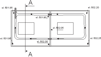
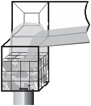
An oil collection pit is a reservoir of complex geometry with inclined surfaces and internal channels (Fig 1.). The bottom of the pit has a high point and a low point, with a flow outlet at the low point. Our model is designed for oil collection pit geometry analysis only and not for design or optimization purposes. One model assumption is that fluid flows from the high point to the low point with depth the same in all channels, an assumption ensured by correct design of the gravity flow channel system. Pits can connect to each other (Fig. 1). Most pit channels are filled with gravel. Some channels may have a perforated pipe to facilitate drainage to an outlet.
 (a)
(a)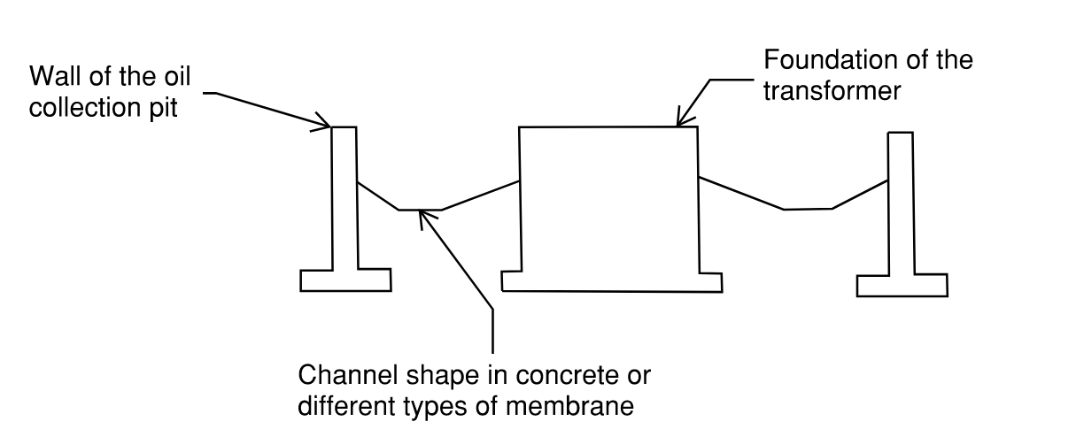 (b)
(b)The volume of water in the pit at time t is:

where
 : volume of water in the pit in previous time step tp, m3
 : volume of water flowing into the pit from another pit over time step ∆t, m3
 : volume of rainwater falling into the pit over time ∆t, m3
 : volume of water overflowing the pit wall, m3
 : volume of water flowing out of the pit over time ∆t through the outlet, m3
The volume of rainwater falling into the pit over time ∆t is:

where
Ab : pit area, m2
I : rain intensity, m/s
The volume of water flowing out of the pit over time ∆t through the outlet is:

where
Q : discharge through the pit outlet, m3/s
Water height in the channels at any moment in time can be determined from the volume of water in the pit at that moment assuming (a) rainwater enters the channels immediately (no flow to electrical devices or other elements) and (b) water height is the same in all channels (uniform flow):

where:
J : number of channels in the pit
Ac : wetted cross-sectional area of channel j, m2
Lc : length of channel j, m
In Eq. (4), the wetted cross-sectional area, in the case of gravel-filled channels, is divided by the porosity of the gravel. If there is a perforated pipe in the channel, then its effect on the final wetted-section surface is also considered geometrically (Fig. 5c).
If water height in the channels exceeds the height of the pit wall, the pit will overflow. The volume of water overflowing is then:
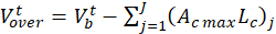
where:
Ac max : full channel j cross-sectional area, m2
Rain flow is unlikely to result in overflow of a pit wall but the equation can be used for analyses of other situations where such a possibility exists—extinguishing a fire, for example.
Note that flow during any one time step is not steady state. Flow velocity in the channels can be calculated approximately only, as follows:
(a) For gravel-filled channels, flow velocity (m/s) is calculated according to Darcy's law:

where:
K : hydraulic conductivity of gravel, m/s
S : slope of channel
Note that vd is the Darcy velocity. Actual velocity in the pore channel, ignoring viscosity, can be calculated using the following formula:

where:
η : porosity of gravel

where:
k : gravel permeability, m2
ρ : water density, 1,000 kg/m3
g : gravity, 9.81 m/s2
µ : water dynamic viscosity, 0.001 Pa·s
The Kozeny-Carman equation [1-4] for permeability of gravel is:

where:
deff : minimum diameter of gravel (m)
Csh : form factor (8 is generally used)
Cpk : packing factor (5 is generally used)
(b) For channels without gravel, flow velocity (m/s) is calculated according to the Manning formula:

where:
R : hydraulic radius, m
n : roughness coefficient, s/m1/3
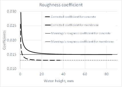
The model takes into account that the roughness coefficient varies with water height in the pits [5]. This coefficient can vary significantly on rough surfaces such as concrete or sprayed membrane when the water is not deep, as in collection pits.
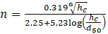
where:
hc : water height in pit channel, m
d50 : average roughness size of flow surface, m
The change in this coefficient with water depth is shown in Fig. 2. With increasing depth, this coefficient becomes equal to Manning’s roughness coefficient.
For a channel with a perforated pipe running along its length, discharge is calculated using Eq. (7) for the part of the flow that goes into the pipe and Eq. (8) for the rest of channel. Water height in the perforated pipe is the same as in the pit.
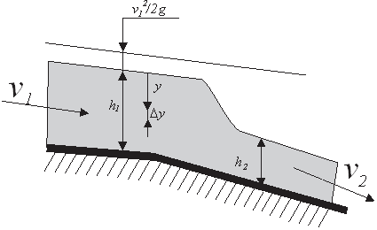
Pit outlets can have different configurations, but the hydraulic flow can generally be described as flow through a weir or an orifice and the general formula for weirs and orifices can be used [6,7]:

where:
H1 : hydraulic head at the high point of the weir, m
H2 : hydraulic head at the bottom point of the weir, m
g : free fall acceleration, m/s2
y : distance from the free surface to the elementary layer of water, m
w : cross-sectional width of the elementary layer, m
dy : height of the elementary layer, m
Application of Eq. (8) to various pit outlet designs is discussed below.
3.1 Flow leaving the pit through a gabion
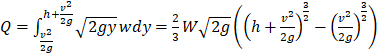
In this design, flow enters the gabion from channels that are generally rectangular in cross-section (Fig. 3a). For such rectangular channels, the general formula of Eq. (12) is transformed as follows (Fig. 3b) [8]:
where:
W : channel cross-sectional width, m
h : height of flow, m
For channels of other cross-sectional shapes or channels ending in a weir, integration over height depending on channel width at different levels is required.
 (a)
(a)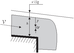 (b)
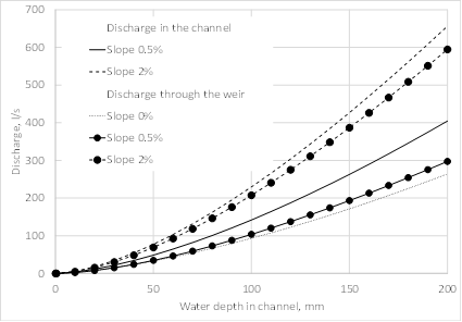
(b)Note that discharge through the weir is different from discharge in the channel. Fig. 4 shows this difference for a range of channel slopes. The channels have a rectangular cross-section 1 m wide and a Manning’s coefficient of 0.013. Fig. 4a shows results for a channel without gravel. Discharge through the weir is greater than channel discharge for the entire range of slopes, consistent with open flow theory [9-10] under the accepted hypotheses. Fig. 4b shows the same comparison of discharges but with the channel filled with gravel 50-100, porosity 0.45. In Eq. (12), only the free surface between the stones needs to be taken into account, with the integral multiplied by porosity. The difference between discharge in the channel and discharge through the weir is more significant in this case. This is because gravel greatly slows down flow in the channel when slopes are small, and the pressure in the pore channels (which affects the velocity of free fall) does not depend on the presence of a gravel skeleton. No flow retardation factors are used in Eq. (12) because the measurements of gravel density and Manning's coefficient are less accurate than the precision this factor can provide.
 (a)
(a)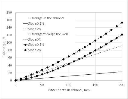 (b)
(b)The flow rate into a gabion is the sum of the flow from all channels connected to it. The capacity of water to infiltrate a gabion is limited by Darcy's law. In this case it is:

where
K : hydraulic conductivity of gabion, m/s
A : surface of gabion, m2
3.2 Outflow through horizontal orifice in the wall
Horizontal orifices in the wall are a common design for pits filled with gravel and connected to other pits (Fig. 5). This type of outlet is considered an orifice in the reservoir if it is completely submerged in water or a weir if the water level is below the top edge of the orifice. The stones are pressed quite tightly against the orifice, reducing the surface available for water drainage depending on gravel porosity. Water level in the downstream pit affects flow in the upstream pit. Used in this case is Dubuat’s formula [11], which regards the overflow as composed of two parts: an upper part treated as flow over a weir and a lower part treated as flow through a submerged orifice. The combination of the two parts yields:


where:
Qu : discharge, upper part of flow, m3/s
Ql : discharge, lower part of flow, m3/s
η : porosity of gravel in the channel
h1 : water height in upper flow pit, m
h2 : water height in lower flow pit, m
v1 : water velocity in upper channel, m/s
D : orifice diameter, m
Note that no correction factors are included in Eq. (15) but they can be added if necessary. When water flows from a pit into a hatch, only the upper part of the flow is considered, and thus Eq. (15) is converted to Eq. (12) for a circular weir [12].
 (a)
(a)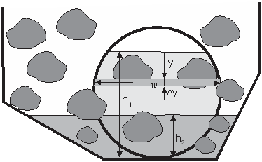 (b)
(b)3.3 Outflow through vertical orifice in channel bottom
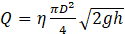
Discharge through a vertical orifice (Fig. 6) is as follows:
3.4 Outflow through a perforated pipe
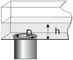
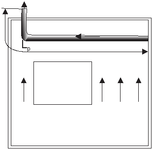
A perforated pipe is often installed along the channel to increase the outflow from a gravel-filled pit (Fig. 7a). Sometimes a short perforated pipe is installed at the low point of the pit (Fig. 7b).
 (a)
(a)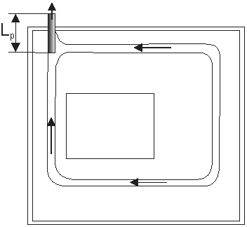 (b)
(b)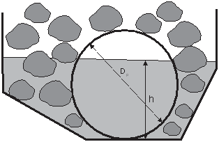 (c)
(c)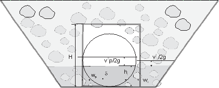 (d)
(d)If outflow is through the pipe only, then outlet discharge is calculated with Eq. (12) using the velocity in the perforated pipe calculated with Eq. (10).
In general case, the discharge is:
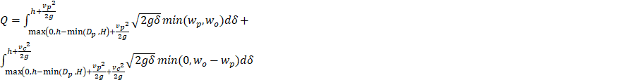
where
h : water depth in channel, m
vp : velocity of flow into perforated pipe, m/s
vc : velocity of flow into channel, m/s
Dp : perforated pipe diameter, m
H : size of vertical outlet (diameter or height), m
wp : cross-sectional width of pipe elementary layer, m
wo : cross-sectional width of outlet elementary layer, m
Outflow at the pit outlet is limited by inflow to the pipe, which is:

where
App : total open area per unit length of pipe, m2/m
Lp : length of perforated pipe, m
Dp : diameter of perforated pipe, m
Ppw : wetted perimeter of perforated pipe, m
Apw : wetted area of perforated pipe, m2
The last term in Eq. (18) is important only for short perforated pipes, where discharge through the main working surface of the pipe is comparable to discharge at the free edge.
3.5 Flow rate through multiple openings
Collection pits often have more than one outlet. The final discharge through multiple outlets is the sum of the discharge at each outlet calculated from its geometric parameters.
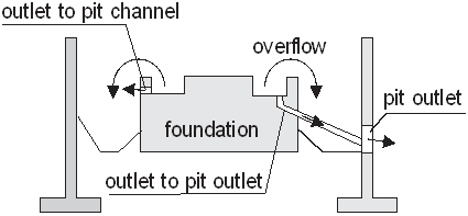
3.6 Transformer foundations with protected channels
The foundation may have small channels without gravel to catch small amounts of oil in a location easily accessible for cleaning. Water also flows through these channels when it rains. In such cases, the foundation is calculated as a separate pit that drains water—either to the outlet of the main pit or to the channels of the main pit depending on the design. In case of the former, the final discharge is the sum of foundation discharge and pit discharge. In case of the latter, water volume from the foundation is added to the water volume in pit, Eq. (1). The channels of the foundation collect water from foundation surface, and the channels of the main pit collect the remaining water. Since the foundation channels are not deep, rainwater overflows through them into the channels of the main pit.
4. Flow in conduit network
Hydraulic calculations for the conduit network are performed using the same methodology as in the SWMM5 software [13]. One-dimensional Saint-Venant equations are used to describe unsteady flow:

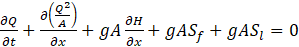
where
A : wetted cross-sectional area of the conduit, m2
Q : discharge, m3/s
t : time, s
x : distance along the conduit, m
H : hydraulic head, m
Sf : friction slope
Sl : local energy loss per unit length of conduit
These equations are supplemented with initial and boundary conditions. The initial condition is a dry conduit before rainfall. The boundary conditions are: (a) for hatches connected to the pits, inflow discharge is as specified in section 3 above; (b) for the outlet to the separator, a free fall flow condition is used. Eqs. (13)-(14) are solved using a method of successive approximations with under relaxation [7].
5. Examples
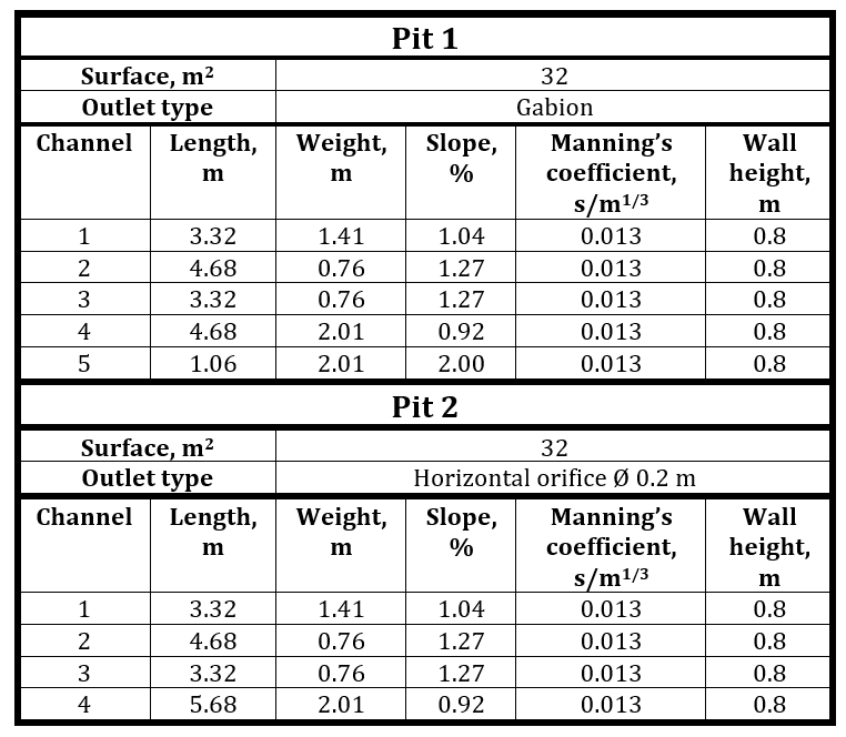
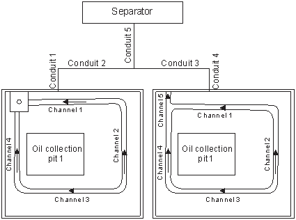
5.1 Analysis of substation with two pits
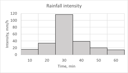
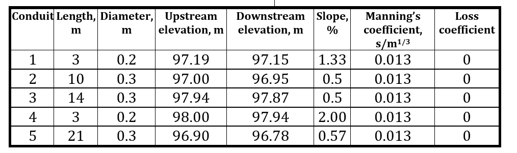
For purposes of this presentation, we use a fictitious substation with only two oil collection pits as an example to demonstrate necessary data and results obtained. The peculiarity of this case is that the oil collection pits have the same hydraulic characteristics, differing only in the design of the outlets. Fig. (9) shows the substation configuration and tables (1)-(2) the geometric characteristics. Fig. (10) shows rainfall intensity.
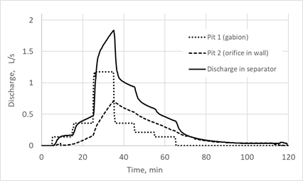
The simulation results clearly show the importance of accurate calculations for outlets. As Fig. 11 shows, water flows from a pit with a gabion much faster than from a pit with an orifice in the wall, increasing the flow rate in the conduit system and into the separator.
 (a)
(a)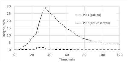 (b)
(b)During the first 30 minutes (Fig. 11a), discharge to the separator is less than flow from pit 1. This is due to the influence of the conduit network. Some substations have long, complex conduit systems that significantly affect flow into the separator. Fulfillment of the law of conservation of mass in the form of volume balance is shown in Fig. 12. Total input volume to each pit during rainfall is the sum of the volumes at the time steps calculated by Eq. 2. Likewise, the sum of the output volumes calculated by Eq. 3 is the total output volume from the pit. Volume flow in the separator at each time step is equal to:

where
Qsep : discharge in separator, m3 (discharge in conduit 5)
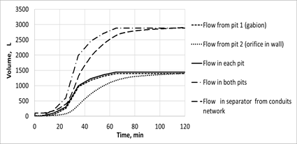
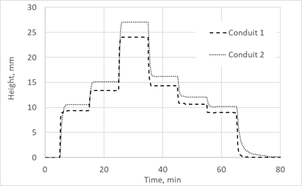
Fig. 13 shows another type of result checking. A stable discharge every 10 minutes from pit 1 (Fig. 12a) makes it possible to use the Manning formula (Eq. 10) for conduits 1 and 2 (Fig. 13). In this case, the Manning formula is an asymptote for Eqs. (19)-(20) once flow stabilizes. Comparison results are shown in Fig. 13b. Discharges obtained with Eq. 20 were calculated for water heights obtained with Eq. 19 and compared with discharges obtained with Eq. 10. As expected, there were differences only when the nature of the flow changed.
 (a)
(a)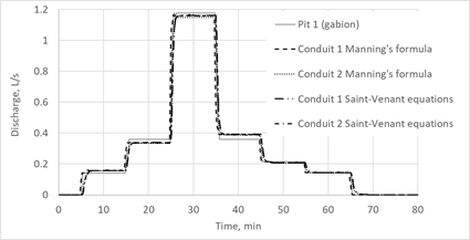 (b)
(b)5.2 ANALYSIS OF SUBSTATION WITH SIX PITS
The vertical outlets at the bottom of the pits are the key feature of this substation, located on the roof of the power plant (Fig. 6). The capacity of these outlets is greater than that of similarly sized wall orifices. Discharge does not depend on flow velocity in the channels.
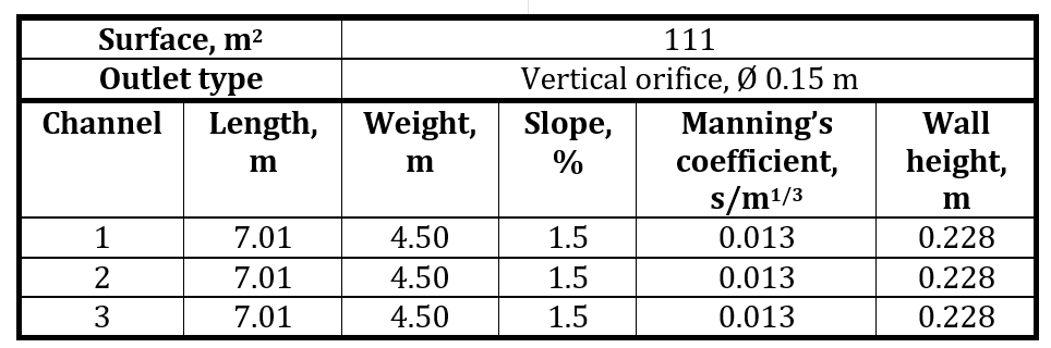
This substation has six identical pits. Table 3 shows the parameters of the pits.
The long and complex piping system slows down the flow. Head loss coefficient is 0.8 for a pipe with a 90° bend at the junction; 0.7 for a trunkline with one lateral; and 1.0 for a junction with three or more entrance lines [14]. Fig. 14 shows the configuration of the substation hydraulic system, and Table 4 gives the conduit parameters.
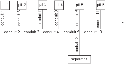
Table 4: Parameters of conduit network
|
Conduit |
Length, m |
Diameter, m |
Upstream elevation, m |
Downstream elevation, m |
Slope, % |
Manning’s coefficient, s/m1/3 |
Loss coefficient |
|
1 |
12 |
100 |
205.63 |
205.51 |
1.00 |
0.011 |
0.8 |
|
2 |
16 |
150 |
205.51 |
205.35 |
1.00 |
0.011 |
0 |
|
3 |
16 |
150 |
205.35 |
205.19 |
1.00 |
0.011 |
0 |
|
4 |
16 |
150 |
205.19 |
205.03 |
1.00 |
0.011 |
0 |
|
5 |
16 |
150 |
205.03 |
204.87 |
1.00 |
0.011 |
0 |
|
6 |
12 |
100 |
205.47 |
205.35 |
1.00 |
0.011 |
0.7 |
|
7 |
12 |
100 |
205.31 |
205.19 |
1.00 |
0.011 |
0.7 |
|
8 |
12 |
100 |
205.15 |
205.03 |
1.00 |
0.011 |
0 |
|
9 |
12 |
100 |
204.99 |
204.87 |
1.00 |
0.011 |
0 |
|
10 |
16 |
100 |
205.03 |
204.87 |
1.00 |
0.011 |
0.7 |
|
11 |
12 |
100 |
205.15 |
205.03 |
1.00 |
0.011 |
0 |
|
12 |
20 |
100 |
204.87 |
204.85 |
1.00 |
0.011 |
1.0 |
According to the Chicago design storm method, a storm with a 2-year return period is considered a light rain and one with a 50-year return period is considered a heavy rain. Fig. 14 shows corresponding hydrographs.
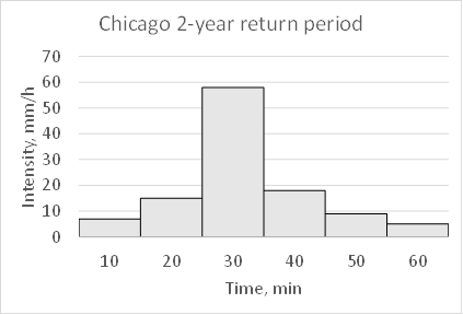 (a)
(a)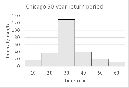 (b)
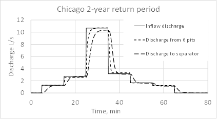
(b)Fig. 15 shows the final discharge for two types of rainfall and compares it with inflow discharge to the system, that is discharge due to rain and discharge outflowing from the six pits. The discharge from the six pits is a boundary condition for the pipe network system. The water does not overflow the pit walls. Fig. 16 shows the volume balance.
 (a)
(a)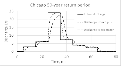 (b)
(b)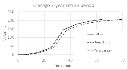 (a)
(a)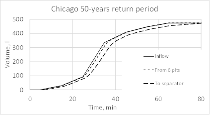 (b)
(b)4. Conclusion
The methodology developed calculates rainwater discharged into a substation’s oil-water separator. Particular attention is paid to accurate calculation of flow through outlets of different design. As shown in the example in the paper, outlet design has a major impact on final discharge from oil collection pits. The empirical and analytical equations used are well known and time-tested, providing a guarantee of results; this is important given that experimentation on real equipment is practically impossible. A volume balance check and comparison with the asymptotic solution using Saint-Venant equations confirmed the reliability of the results. The method is not limited in terms of number and cross-sectional shape of the oil collection pit channels or outlet design. The use of full one-dimensional Saint-Venant equations makes it possible to calculate conduit networks of any complexity: networks with a series of pits connected both directly and via conduits; networks with parallel sections of conduits of different diameters or made of different materials; conduits with negative and zero slopes; wells connected to three or more conduits at different levels; etc. The model is a useful tool for quick and accurate prediction of water discharge to an oil-water separator. The next step will be to model oil-water interaction in the substation hydraulic system, making it possible to simulate liquid with a high oil content and predict the concentration of oil in the flow into the separator.
References
[1] Kozeny J. (1927) "Ueber kapillare Leitung des Wassers im Boden." Sitzungsber Akad. Wiss., Wien, 136(2a): 271-306.
[2] Carman P.C. (1937) "Fluid flow through granular beds." Transactions, Institution of Chemical Engineers, London, 15: 150-166.
[3] Urumović K., Urumović Sr. K., (2016) "The referential grain size and effective porosity in the Kozeny-Carman model", Hydrology and Earth System Sciences 20, pp 1669-1680
View Article
[4] Poster L.B., Ritzi R.W., Mastera L.J., Dominic D.F., Ghanbarian-Alavijeh B., (2012) "The Kozeny-Carman Equation with a Percolation Threshold", Groundwater, v. 51, issue 1, pp. 92-99
View Article
[5] Blodgett J.C. (1986) "Rock riprap design for protection of stream Channels near highway structures," Water-Resources Investigations Report 86-4127, Sacramento, California.
[6] Horton R.E. (1906) Weir Experiments, Coefficients, and Formulas. Washington.
[7] Herschy, R.W. (1998). Flow through weirs, flumes, orifices, sluices and pipes. In: Encyclopedia of Hydrology and Lakes. Encyclopedia of Earth Science. Springer, Dordrecht .
[8] Wang Y., Lv M., Wang W., Meng M., (2024) "Discharge Formula and Hydraulics of Rectangular Side Weirs in the Small Channel and Field Inlet", Water, 16(5), 713
View Article
[9] Henderson F.M. (1966) Open Channel Flow, Macmillan Publishing, Chapter 1.
[10] Moglen G.E., (2022) "Fundamentals of Open Channel Flow", CRC Press
View Article
[11] Villemoute J.R. (1947) "Submerged-weir discharge studies," Engineering News Record, 139(26): 866-869.
[12] Vatankhah A.R. (2010) "Flow measurement using circular sharp-crested weirs", Flow Measurement and Instrumentation V. 21 pp. 118-122
View Article
[13] James W., Rossman L.A. and R.C. James (2010). User's guide to SWMM5, 13th edition. Guelph, Ontario: CHI Press.
[14] https://vanoengineering.wordpress.com/
View Article
[1] Kozeny J. (1927) "Ueber kapillare Leitung des Wassers im Boden." Sitzungsber Akad. Wiss., Wien, 136(2a): 271-306.
[2] Carman P.C. (1937) "Fluid flow through granular beds." Transactions, Institution of Chemical Engineers, London, 15: 150-166.
[3] Urumović K., Urumović Sr. K., (2016) "The referential grain size and effective porosity in the Kozeny-Carman model", Hydrology and Earth System Sciences 20, pp 1669-1680 View Article
[4] Poster L.B., Ritzi R.W., Mastera L.J., Dominic D.F., Ghanbarian-Alavijeh B., (2012) "The Kozeny-Carman Equation with a Percolation Threshold", Groundwater, v. 51, issue 1, pp. 92-99 View Article
[5] Blodgett J.C. (1986) "Rock riprap design for protection of stream Channels near highway structures," Water-Resources Investigations Report 86-4127, Sacramento, California.
[6] Horton R.E. (1906) Weir Experiments, Coefficients, and Formulas. Washington.
[7] Herschy, R.W. (1998). Flow through weirs, flumes, orifices, sluices and pipes. In: Encyclopedia of Hydrology and Lakes. Encyclopedia of Earth Science. Springer, Dordrecht .
[8] Wang Y., Lv M., Wang W., Meng M., (2024) "Discharge Formula and Hydraulics of Rectangular Side Weirs in the Small Channel and Field Inlet", Water, 16(5), 713 View Article
[9] Henderson F.M. (1966) Open Channel Flow, Macmillan Publishing, Chapter 1.
[10] Moglen G.E., (2022) "Fundamentals of Open Channel Flow", CRC Press View Article
[11] Villemoute J.R. (1947) "Submerged-weir discharge studies," Engineering News Record, 139(26): 866-869.
[12] Vatankhah A.R. (2010) "Flow measurement using circular sharp-crested weirs", Flow Measurement and Instrumentation V. 21 pp. 118-122 View Article
[13] James W., Rossman L.A. and R.C. James (2010). User's guide to SWMM5, 13th edition. Guelph, Ontario: CHI Press.
[14] https://vanoengineering.wordpress.com/ View Article