International Journal of Civil Infrastructure (IJCI)
ISSN: 2563-8084

Volume 8 - Year 2025- Pages 01-09
DOI: 10.11159/ijci.2025.001
Finite Element Investigation on the Response of Tunnel Rock-Supports in Zones Subjected To Squeezing Occurrence
Gianluca Bella1-2, Giulio Antonucci2, Gennaro Scognamiglio2
1 University of Applied Sciences and Arts of Southern Switzerland (SUPSI)
Via Flora Ruchat-Roncati 15, Mendrisio, Switzerland, 6850
gianluca.bella@supsi.ch
2 Pini Group SA, Department of Tunnels and Underground Works
Via Besso 7, Lugano, Switzerland, 6900
3 Freelance, Genova, Italy, 16100
ing.antonuccigiulio@libero.it, ing_scognamiglio@libero.it
Abstract - The minimization in the travel time for people and good is a fundamental factor in the economic progress of any nation. Achieving this objective can be realized through tunnelling, which often involves digging at significant depths. When tunnelling at high depths, the rock masses, especially if they are weak, can generate significant stress, so leading to substantial deformation during excavation operations. These large deformations around the tunnel frequently exceed the capacity of standard rock support systems, making it challenging to maintain the tunnel's stability and safety during construction. The current study deals with Finite Element analysis to investigate the stress-strain behaviour of the rock support of a deep tunnel under squeezing conditions. The rock support performances are evaluated and compared considering several fracturing conditions by means of a wide GSI range at simulating a decrease of the rock mass properties due to the proximity of tectonized zones. Different rock mass types are also studied with variations of mi parameter and uniaxial compressive strength. The performances of the rock supports - sliding or stiff ribs - are evaluated and compared in terms of stresses and strain acting on.
Keywords: Squeezing, tunnelling, weak conditions, sliding ribs
© Copyright 2025 Authors - This is an Open Access article published under the Creative Commons Attribution License terms. Unrestricted use, distribution, and reproduction in any medium are permitted, provided the original work is properly cited.
Date Received: 2024-08-29
Date Revised: 2025-01-08
Date Accepted: 2025-01-20
Date Published: 2025-01-23
1. Introduction
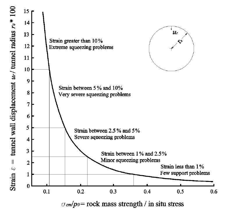
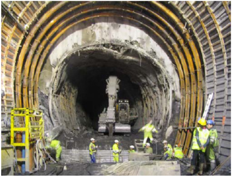
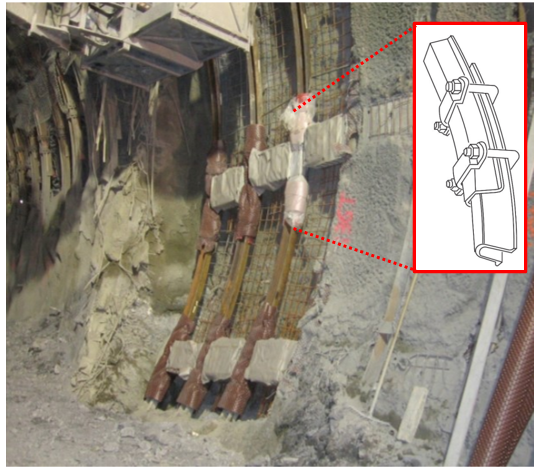
One of the primary challenges encountered when tunneling through mountainous regions, is the squeezing behavior of some encountered rock masses, as demonstrated by over a century of experience ([1], [2]). Rock squeezing refers to significant, time-dependent deformations that occur around the tunnel, primarily associated with creep resulting from exceeding critical shear stress, and these deformations may halt during construction or continue over an extended period ([3]). According to [4], the rate of deformation, the tunnel convergence and the size of the yielding zone surrounding the tunnel are influenced by factors such as geological conditions, in-situ stresses in relation to rock mass strength, groundwater flow, pore pressure, and rock mass properties (Fig.1). The response of rock to squeezing is known to be affected by the type and structure of the rock: in squeezing zones, the rock is typically highly fractured and jointed, with low strength. Furthermore, the overburden also plays a significant role, and squeezing behavior may occur in a tunnel once a certain overburden threshold is exceeded. The literature documents various instances of squeezing occurring during the excavation of deep tunnels (Fig.2), including cases like the Saint Martin La Porte access adit ([5]) and the Monte Ceneri base Tunnel ([6]).
 (a)
(a) (b)
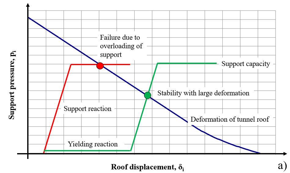
(b)Squeezing is linked to the excavation technique, tunnelling sequences, and supporting methods, making the selection of rock support a crucial factor for ensuring safety and optimizing the design. Flexible rock supports permit a certain degree of displacement in the rock mass within defined limits, leading to an equilibrium between the rock mass and the support as shown by the green point in Figure 3 which is below the capacity of the rock support. On the other hand, if the rock deformations are restricted by the adoption of rigid support systems, squeezing will cause the support to gradually accumulate load over time, with the equilibrium pressure reaching the maximum capacity, which could ultimately result in failure of the support system (red point in the same picture).
 (a)
(a)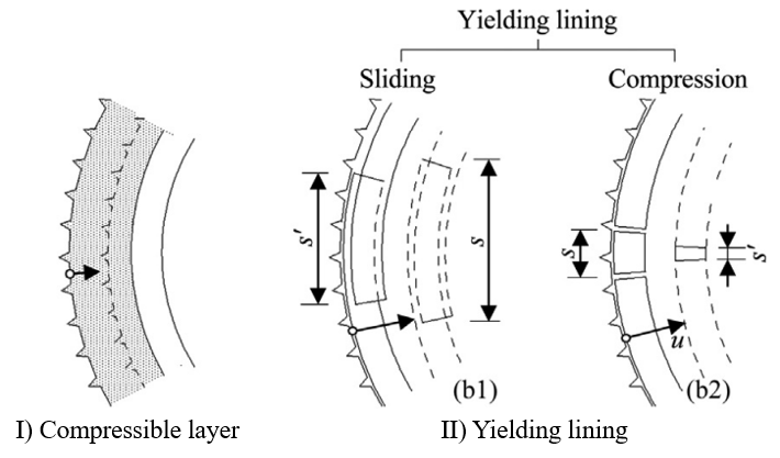 (b)
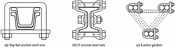
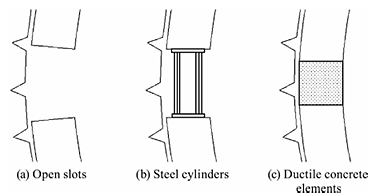
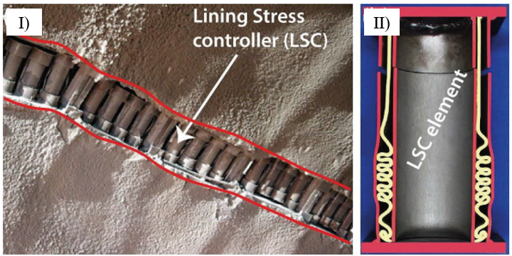
(b)Some details of flexible supports are given in the following picture: more information can be found in [9].
In this context, the present study investigates the performance of rigid versus sliding rock supports under squeezing conditions, which are expected when tunnelling at hight depths and high stress levels. Two scenarios are considered: one involving various states of rock fracturing (‘Simulation n.1’) and another focused on different types of weak rock masses (‘Simulation n.2’) that lead to squeezing. The performances associated with using rigid or sliding ribs are evaluated and compared in terms of the strain and stresses exerted on the rock supports.
2. Numerical analysis
2.1 Finite element modelling and hypothesis
The cross-section of a circular, deep tunnel, radius RT = 5.0m, overburden H=600m - under plane strain conditions and a constant stress state - was modelled by using the finite element software RS2v.9.0 (RocScience) as shown in Figure 6. Six noded, graded triangular meshes (total 10’000), progressively refined near significant clusters, were adopted. The shape of the mesh (triangular) has been adopted because of the simple geometry of the problem and since it allows a reduction of the computation time. Boundary conditions were defined with hinges along all sides of the model to avoid horizontal/vertical displacements, and the model dimensions (130x130m) were chosen to prevent numerical side effects. The rock mass considered for ‘Simulation n.1’ consists of Shists (average value of the modulus ratio MR=550), while for the ‘Simulation n.2’ were analyzed the following rock types: shale, phyllite, metabasics, schists, gneiss, and altered diorite (MR=150-1100). Knowledge of the uniaxial compressive strength of the intact rock and MR allows to estimate the elastic modulus of the intact rock (Eq.(1)), leading to obtaining the deformability modulus of the rock mass depending on the GSI and disturbance factor D (Eq.(2)). Moreover, quantification of the squeezing behavior requires the knowledge of the rock mass uniaxial compressive strength according to Eq.(3) proposed by [7] depending on the Hoek-Brown parameter, on the uniaxial compressive strength of intact rock, and Geological Strength Index.

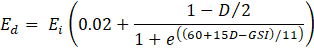
where MR is the modulus ratio, UCS is the uniaxial compressive strength of the intact rock, Ed is the deformability modulus of the rock mass, Ei is the elastic modulus of the intact rock, GSI is Geological Strength Index, D is the disturbance factor, σcm is rock mass uniaxial compressive strength, mi is the Hoek & Brown parameter of the intact rock. An elastic-perfectly plastic Hoek-Brown failure criteria has been adopted. Dry conditions were assumed for all the analyses, while the tunnel excavation was simulated step by step (Tab.1).
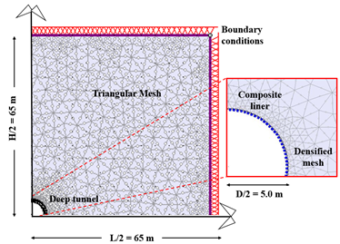
Table 1: Finite element model steps and description.
|
Step |
Description (X=tunnel face distance) |
|
1 |
in-situ state of stress, pi/p0=1.0 |
|
2 |
tunnel face excavation, X=0.0m, pi/p0(X) |
|
3 |
temporary lining installation, X=1.0m, pi/p0(X) |
|
4 |
tunnel excavation advance, X=2.0m, pi/p0(X) |
|
5 |
shotcrete curing at 5 days, X=5.0m, pi/p0(X) |
|
6 |
shotcrete curing at 7 days, X=10.0m, pi/p0(X) |
|
7 |
final lining installation, far from the tunnel face, distance X=20.0m, pi/p0=0 |
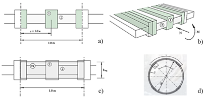
A wide range of GSI values, from 25 to 45 (analysis A → analysis E), was employed in 'Simulation n.1' to capture varying fracturing conditions. To simulate the impact of different poor-quality rock masses, ''Simulation n.2' considered a variable range of mi values (8-20) and uniaxial compressive strength (UCS) values (10-15MPa) across analyses A to I. In these conditions “extreme and very severe squeezing problems” are expected (Fig.1). The unit weight (γ), GSI, the Hoek & Brown mi parameter (intact rock), UCS, Poisson’s ratio (v), deformability modulus (Ed), rock mass strength (σcm), initial stress state (p0), and the coefficient of earth pressure at rest (k0) are detailed in Table 2 and Table 3 for ''Simulation n.1' and ''Simulation n.2', respectively. The rock support (primary lining) was modelled as a ‘standard beam’ (Tab.4). The equivalent section per meter length includes a 0.2m thick shotcrete layer and double IPN160 ribs spaced at 1.5m intervals. To represent the presence of sliding ribs in the deformable lining, four circumferential sliding slots (each 0.10m long) were incorporated, allowing for a circumferential strain of 1.2%. The final tunnel lining consists of a steel-reinforced concrete section (Tab.5).
Table 2: ‘Simulation n.1’. Rock mass parameters (γ=27kN/m3, mi=20, UCS=12MPa, v=0.30, p0=16.2MPa, k0=1).
|
Analysis → |
A |
B |
C |
D |
E |
|
GSI [-] |
25 |
30 |
35 |
40 |
45 |
|
Ed [MPa] |
395 |
537 |
750 |
1050 |
1480 |
|
σcm [MPa] |
0.99 |
1.17 |
1.37 |
1.60 |
1.88 |
|
σcm/p0 [-] |
0.06 |
0.07 |
0.08 |
0.10 |
0.12 |
Table 3: ‘Simulation n.2’. Rock mass parameters of shist, phyllite mi=8, schists mi=10, metabasics, gneiss and altered diorite mi=20 (γ=27kN/m3, v=0.30, p0=16.2MPa, k0=1).
|
Analysis → |
A |
B |
C |
D |
E |
|
GSI [-] |
40 |
40 |
40 |
40 |
40 |
|
mi [-] |
8 |
10 |
20 |
8 |
10 |
|
UCS MPa] |
10 |
10 |
10 |
12 |
12 |
|
Ed [MPa] |
878 |
878 |
878 |
1053 |
1053 |
|
σcm [MPa] |
0.87 |
0.96 |
1.34 |
1.04 |
1.15 |
|
σcm/p0 [-] |
0.05 |
0.06 |
0.08 |
0.06 |
0.07 |
(part 1/2)
|
Analysis → |
F |
G |
H |
I |
|
GSI [-] |
40 |
40 |
40 |
40 |
|
mi [-] |
20 |
8 |
10 |
20 |
|
UCS [MPa] |
12 |
15 |
15 |
15 |
|
Ed [MPa] |
1053 |
1317 |
1317 |
1317 |
|
σcm [MPa] |
1.60 |
1.30 |
1.44 |
2.00 |
|
σcm/p0 [-] |
0.10 |
0.08 |
0.09 |
0.12 |
(part 2/2)
Table 4: Equivalent rock support parameters: elastic modulus (Eeq), thickness (heq), area (Aeq), inertia (Ieq), Poisson’s ratio (v), circumferential strain (εc).
|
|
Eeq [MPa] |
heq [m] |
Aeq [m2] |
Ieq [m4] |
v [-] |
εc [%] |
|
Rock support type A: stiff ribs |
4435 |
0.21 |
0.215 |
0.000826 |
0.20 |
- |
|
Rock support type B: sliding ribs |
4435 |
0.21 |
0.215 |
0.000826 |
0.20 |
1.2 |
Table 5: Final lining parameters: elastic modulus (E), spacing (s), diameter (Φ), rebar depth (d), thickness (h), area (A), inertia (I), Poisson’s ratio (v), compressive strength (σc), tensile strength (σt).
|
|
E [GPa] |
s [m] |
Ф [mm] |
d [mm] |
h [m] |
|
Reinforcement (rebar B450C, 2 layers) |
200 |
0.25 |
16 |
0.9 |
- |
|
Concrete C20/25 |
30 |
- |
- |
- |
1.0 |
(part 1/2)
|
|
A [mm2/m] |
I [m4] |
v [-] |
σc [MPa] |
σt [MPa] |
|
Reinforcement (rebar B450C, 2 layers) |
803 x 2 |
8.14∙ 10-5 |
0.25 |
450 |
450 |
|
Concrete C20/25 |
- |
- |
0.15 |
25 |
3 |
(part 2/2)
2.2 Design approach
FE analyses are conducted to assess the performances either for rigid ribs or sliding rock supports, following the procedure listed below:
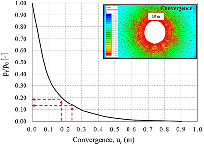
- An initial Convergence-Confinement two-dimensional analysis of the unsupported tunnel is performed with 10 calculation stages (pi/p0 = 1.0, pi/p0 = 0.8, pi/p0 = 0.4, pi/p0 = 0.2, pi/p0 = 0.1, pi/p0 = 0.08, pi/p0 = 0.04, pi/p0 = 0.02, pi/p0 = 0.01, and pi/p0 = 0). So, the maximum convergence (umax) and the plastic radius (RP) of the unsupported tunnel at the final stage are estimated (Fig.8);
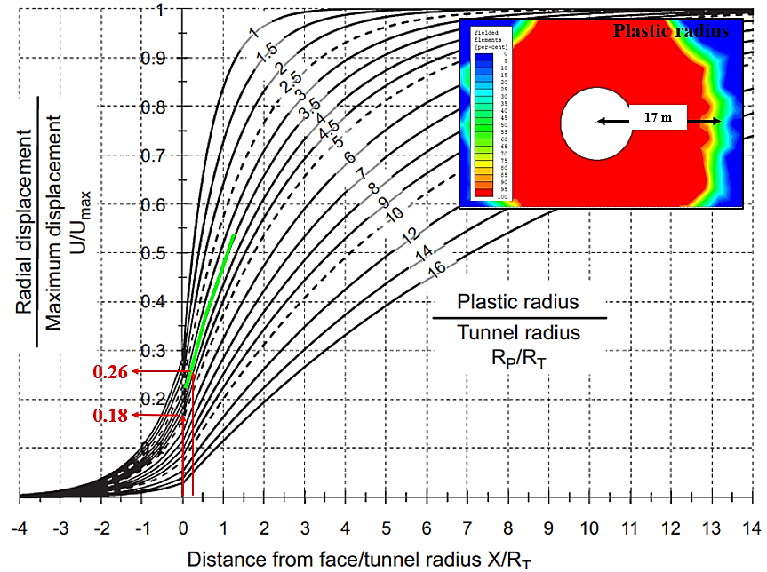
- The method outlined by [12] is used to determine the tunnel convergence (ur) at specified distances from the tunnel face (i.e., tunnel face: X = 0m; installation of the rock support: X = 1m), based on the ratio RP/RT, as shown in Fig.9;
- Following the convergence-confinement approach ([13]), radial displacements above estimated are used to determine the ratio pi/p0 = (1-λ) at both the tunnel face and the rock support installation, enabling the calculation of the relaxation factor λ(X), as shown in Fig.8;
- The relaxing factors allowed to perform a second series of FE analyses made of two models (Tab.1) to compare the two different rock supports.
3. Results
Main outcomes both for simulation n.1 and simulation n.2 are provided in the following chapters.
3.1 Simulation n.1
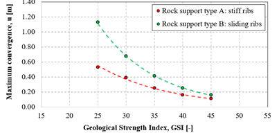
Table 6 presents a comparison of the FE results, considering either stiff ribs (rock support type A), or sliding ribs (rock support type B). Figure 10(top) shows the stress state MN acting on the rock support type A (represented by red symbols for stiff ribs) and type B (represented by green symbols for deformable ribs) as a function of rock mass fracturing, depicted in the interaction diagram. The safety level is also evaluated, as shown in the same Figure (middle). Due to the increased radial displacement allowed by deformable ribs, they are subjected to a lower state of stress compared to stiff ribs. Furthermore, the rock mass fracturing has little impact on the safety level. These findings suggest that, within the considered loading conditions, tunnel shape, and stress state, deformable ribs offer a higher safety level than rock support type A. In both cases, the radial displacement increases as the quality of the rock mass decreases, whether sliding or stiff rock supports are used, as illustrated in Figure 10(bottom). A significant reduction in radial displacement with improved rock quality is more noticeable when sliding ribs are used instead of stiff ribs. The differences between stiff and sliding ribs are more evident for GSI values between 25-35 (indicating very poor rock mass quality), while for poor to medium rock mass quality, the differences become less significant.
Table 6: Simulation n.1, stiff and sliding ribs: maximum convergence at final lining installation (u), plastic radius (RP), axial force (Nmax), and bending moment (Mmax).
|
Analysis |
|
|
Rock support type A: stiff ribs |
|||
|
Ed [MPa] |
GSI [-] |
u [m] |
RP [m] |
Nmax [MN] |
Mmax [MNm] |
|
|
A |
395 |
25 |
0.53 |
10.50 |
12.10 |
5.00 |
|
B |
537 |
30 |
0.39 |
10.10 |
9.80 |
3.50 |
|
C |
750 |
35 |
0.25 |
9.90 |
9.31 |
3.40 |
|
D |
1050 |
40 |
0.16 |
8.60 |
9.20 |
3.20 |
|
E |
1480 |
45 |
0.11 |
8.00 |
8.30 |
3.00 |
(part 1/2)
|
Analysis |
|
|
Rock support type B: sliding ribs |
|||
|
Ed [MPa] |
GSI [-] |
u [m] |
RP [m] |
Nmax [MN] |
Mmax [MNm] |
|
|
A |
395 |
25 |
1.13 |
15.00 |
2.94 |
20.00 |
|
B |
537 |
30 |
0.68 |
13.20 |
3.30 |
16.00 |
|
C |
750 |
35 |
0.41 |
11.70 |
3.20 |
12.00 |
|
D |
1050 |
40 |
0.25 |
10.40 |
3.10 |
9.00 |
|
E |
1480 |
45 |
0.16 |
9.90 |
2.95 |
7.00 |
(part 2/2)
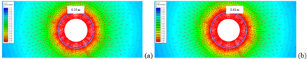
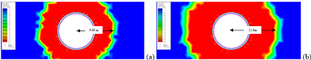
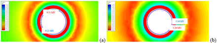
Numerical outputs are provided with their characteristic values (FE analyses performed under GSI=35), as shown in Fig.11-14.
3.2 Simulation n.2
Table 7 provides a summary of the comparison between numerical results obtained from 'Simulation n.2', considering rock support type A (stiff ribs) and type B (sliding ribs). The comparison includes maximum convergence at the final lining installation (u), plastic radius (RP), and characteristic values of the maximum axial force (Nmax) and maximum bending moment (Mmax).
Table 7: Comparison between stiff and sliding ribs in terms of maximum convergence at final lining installation (u), plastic radius (RP), maximum axial force (Nmax), maximum bending moment (Mmax).
|
Analysis |
|
|
|
Rock support type A: stiff ribs |
|||
|
UCS [MPa] |
mi [-] |
Ed [MPa] |
u [m] |
RP [m] |
Nmax [MN] |
Mmax [MNm] |
|
|
A |
10 |
8 |
878 |
0.34 |
14.00 |
14.10 |
4.00 |
|
B |
10 |
0.30 |
12.00 |
12.80 |
5.00 |
||
|
C |
20 |
0.21 |
9.70 |
9.40 |
5.00 |
||
|
D |
12 |
8 |
1053 |
0.25 |
12.50 |
13.60 |
5.00 |
|
E |
10 |
0.24 |
11.60 |
11.50 |
5.00 |
||
|
F |
20 |
0.16 |
8.80 |
8.90 |
9.00 |
||
|
G |
15 |
8 |
1317 |
0.19 |
11.60 |
11.15 |
5.00 |
|
H |
10 |
0.16 |
10.40 |
11.00 |
5.00 |
||
|
I |
20 |
0.12 |
8.40 |
8.00 |
6.00 |
||
(part 1/2)
|
Analysis |
|
|
|
Rock support type B: sliding ribs |
|||
|
UCS [MPa] |
mi [-] |
Ed [MPa] |
u [m] |
RP [m] |
Nmax [MN] |
Mmax [MNm] |
|
|
A |
10 |
8 |
878 |
0.94 |
22.00 |
3.40 |
12.00 |
|
B |
10 |
0.71 |
17.80 |
3.40 |
13.00 |
||
|
C |
20 |
0.35 |
11.50 |
3.20 |
27.00 |
||
|
D |
12 |
8 |
1053 |
0.63 |
19.00 |
3.40 |
10.00 |
|
E |
10 |
0.49 |
16.00 |
3.25 |
10.00 |
||
|
F |
20 |
0.25 |
10.60 |
3.10 |
28.00 |
||
|
G |
15 |
8 |
1317 |
0.39 |
15.50 |
3.30 |
10.00 |
|
H |
10 |
0.31 |
14.20 |
3.30 |
15.00 |
||
|
I |
20 |
0.17 |
9.80 |
3.00 |
30.00 |
||
(part 2/2)
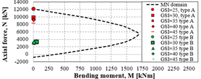
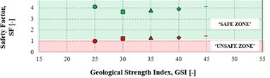
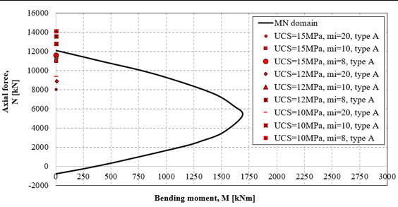
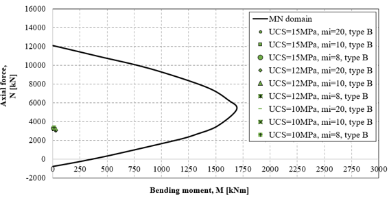
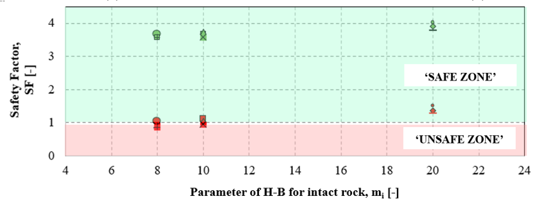
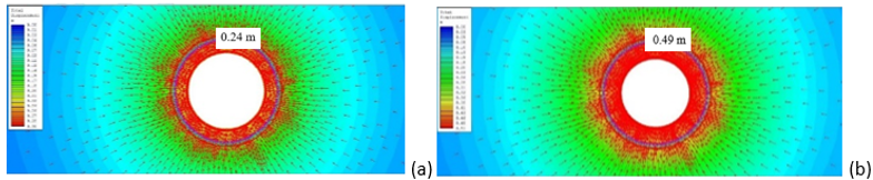
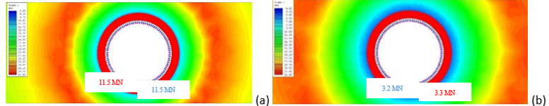
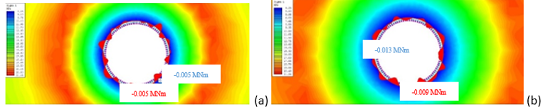
Figure 15 illustrates the effects of variations in the UCS and the mi H-B parameter on the MN domain and the safety factor of the support. Figure 15(top) and Figure 14(middle) show the stress state acting on rock support type A (red symbols: stiff ribs) and type B (green symbols: deformable ribs), respectively. The isotropic stress state, model symmetry, and the tunnel's circular shape resulted in relatively low bending moments when compared to the axial forces acting on the rock supports. As depicted in Figure 14(bottom), variations in mi and UCS representing different poor-quality rock masses do not substantially impact the safety factor for sliding ribs (type B, green symbols). However, for stiff ribs (type A, red symbols), there is an observed increase in the safety factor of approximately 40%. In the case of deformable ribs, the stress state is lower than that of stiff ribs due to the higher convergence allowed by the yielding system. Therefore, under the conditions considered in this study, rock support type B offers a higher safety level than stiff ribs when squeezing conditions are expected.
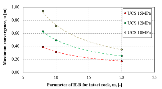
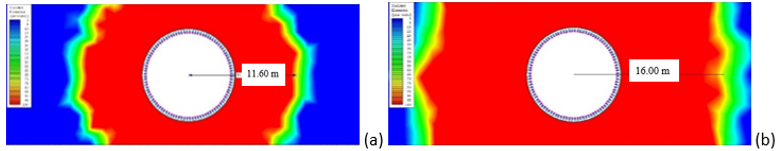
The maximum convergences for rock support types A and B are presented in Figure 16 top and bottom, respectively, based on variations in UCS and mi. For very weak-to-poor quality rock mass (e.g., UCS=10 MPa and mi=8-15), considerable convergences ranging from 0.34 to 0.25m (for stiff ribs) or from 0.90 to 0.50 m (for sliding ribs) are observed. In cases of poor-to-medium rock mass quality (e.g., UCS=12-15MPa and mi=15-20), the differences in convergence are minimal. As the rock mass quality improves (from UCS=12MPa-15MPa and mi=8 to 20), the radial displacement decreases, with a more significant reduction in convergences for sliding ribs (about 2.5 times) compared to stiff ribs (1.5 times), especially when UCS remains constant, and mi varies.

Numerical results are also presented for analyses conducted with GSI=40, UCS=12MPa, and mi=10, as illustrated in Figures 17-20.
4. Conclusion
This study provided an insight into the stress-strain behavior of a deep, circular tunnel cut through a weak rock mass. It also explores the safety levels associated with various types of rock supports and rock mass characteristics, based on finite element analysis. This helps to draw some preliminary suggestions regarding the choice between yielding or rigid rock supports in scenarios involving squeezing behavior. According to ‘Simulation n.1’, the fracturing of the rock mass does not appear to significantly influence the safety level, while deformable supports are found to offer better safety compared to rigid ones. Additionally, ‘Simulation 2’ reveals that yielding supports are more responsive when dealing with weak or poor-quality rock masses. This is because sliding elements allow for larger convergences and result in a lower stress state, thus improving the safety factor. In contrast, the safety criteria are not met with stiff ribs in weak-poor quality rock. However, for rock masses of medium quality, both stiff and sliding ribs maintain an acceptable safety factor, which increases notably as the geo-mechanical parameters improve.
The above results and so effectiveness in adopting yielding supports when squeezing behavior was expected, have been confirmed by recent tunnelling experiences given by literature ([6]).
Additional investigations could be carried out by employing more advanced constitutive models that incorporate long-term behavior, such as creep, or by examining the tunnel excavation process under an anisotropic stress state. These enhanced models would offer a more comprehensive understanding of the material's response over extended periods and in complex stress conditions, ultimately leading to more accurate predictions of the tunnel's stability and performance throughout its construction and operational lifespan.
References
[1] G. Antonucci, G. Bella, G. and Scognamiglio, “Numerical Analysis of Tunnel Supports in Weak Ground Conditions and High Stress Levels”, in Proceeding of the 5th International Conference on Civil Engineering Fundamentals and Applications (ICCEFA 2024), Lisbon, Portugal, vol. 01, pp, 1-8, 2024.
View Article
[2] G. Scognamiglio, G. Antonucci, and G. Bella, "On the stress-strain response of deep tunnel in squeezing conditions: numerical analysis for the design of rock supports", in Proceeding of the 10th International Conference on Geotechnical Research and Engineering (ICGRE 2025), Barcelona, Spain, vol. 01, pp. 1-8, 2025.
[3] G. Barla, "Squeezing rocks in tunnels", ISRM News Journal, 3/4, pp. 44-49, 1995.
[4] W. Steiner, "Tunnelling in squeezing rocks: case histories", Rock Mech. and Rock Eng., vol. 29, pp. 211-246, 1996.
View Article
[5] G. Barla, "Innovative tunneling construction method to cope with squeezing at the Saint Martin La Porte access adit (Lyon-Turin Base Tunnel)", in Proceedings of the Eurock 2009 Rock Engineering in Difficult Ground Conditions, Dubrovnik, Croatia, vol. 1, pp. 1-10, 2009.
[6] D. Merlini, D. Stocker, M. Falanesca and R. Schuerch, "The Ceneri Base Tunnel: Construction experience with the Southern Portion of the Flat Railway Line Crossing the Swiss Alps", Engineering, vol. 1, no. 2, pp. 235-248, 2018.
View Article
[7] E. Hoek and P. Marinos "Predicting tunnel squeezing problems in weak heterogeneous rock masses", Tunnels and Tunnelling International, vol. 32, no. 11, pp. 45-51, 2000.
[8] K. Kovári, C. Amstad and G. Anagnostou, "Design / Construction methods Tunnelling in swelling rocks", in Proceeding of the 29th U.S. Symposium Key Questions in Rock Mechanics, Minnesota, pp. 17-32, 1988.
[9] M. Ghorbania, K. Shahriara, M. Sharifzadehb and R. Masoudic, “A critical review on the developments of rock support systems in high stress ground conditions“, International Journal of Mining Science and Technology, vol. 30, pp. 555–572, 2020.
View Article
[10] W. Schubert, "Dealing with Squeezing Conditions in Alpine Tunnels", Rock Mech Rock Eng, vol. 29, no.03, pp.145-53, 1996.
View Article
[11] K. Kovári, "Method and device for stabilizing a cavity excavated in underground construction". US Patent 20050191138, 2005.
[12] N. Vlachopoulos and M.S. Diederichs, "Improved longitudinal displacement profiles for convergence confinement analysis of deep tunnels", Rock Mechanics and Rock Engineering, vol. 42, no.2, pp. 131-146, 2009.
View Article
[13] M. Panet and A. Guenot, "Analysis of convergence behind the face of a tunnel", in Proceeding of the International Symposium Tunnelling, (IST'82), The Institution of Mining and Metallurgy, London, pp. 197-204, 1982.
[1] G. Antonucci, G. Bella, G. and Scognamiglio, “Numerical Analysis of Tunnel Supports in Weak Ground Conditions and High Stress Levels”, in Proceeding of the 5th International Conference on Civil Engineering Fundamentals and Applications (ICCEFA 2024), Lisbon, Portugal, vol. 01, pp, 1-8, 2024. View Article
[2] G. Scognamiglio, G. Antonucci, and G. Bella, "On the stress-strain response of deep tunnel in squeezing conditions: numerical analysis for the design of rock supports", in Proceeding of the 10th International Conference on Geotechnical Research and Engineering (ICGRE 2025), Barcelona, Spain, vol. 01, pp. 1-8, 2025.
[3] G. Barla, "Squeezing rocks in tunnels", ISRM News Journal, 3/4, pp. 44-49, 1995.
[4] W. Steiner, "Tunnelling in squeezing rocks: case histories", Rock Mech. and Rock Eng., vol. 29, pp. 211-246, 1996. View Article
[5] G. Barla, "Innovative tunneling construction method to cope with squeezing at the Saint Martin La Porte access adit (Lyon-Turin Base Tunnel)", in Proceedings of the Eurock 2009 Rock Engineering in Difficult Ground Conditions, Dubrovnik, Croatia, vol. 1, pp. 1-10, 2009.
[6] D. Merlini, D. Stocker, M. Falanesca and R. Schuerch, "The Ceneri Base Tunnel: Construction experience with the Southern Portion of the Flat Railway Line Crossing the Swiss Alps", Engineering, vol. 1, no. 2, pp. 235-248, 2018. View Article
[7] E. Hoek and P. Marinos "Predicting tunnel squeezing problems in weak heterogeneous rock masses", Tunnels and Tunnelling International, vol. 32, no. 11, pp. 45-51, 2000.
[8] K. Kovári, C. Amstad and G. Anagnostou, "Design / Construction methods Tunnelling in swelling rocks", in Proceeding of the 29th U.S. Symposium Key Questions in Rock Mechanics, Minnesota, pp. 17-32, 1988.
[9] M. Ghorbania, K. Shahriara, M. Sharifzadehb and R. Masoudic, “A critical review on the developments of rock support systems in high stress ground conditions“, International Journal of Mining Science and Technology, vol. 30, pp. 555–572, 2020. View Article
[10] W. Schubert, "Dealing with Squeezing Conditions in Alpine Tunnels", Rock Mech Rock Eng, vol. 29, no.03, pp.145-53, 1996. View Article
[11] K. Kovári, "Method and device for stabilizing a cavity excavated in underground construction". US Patent 20050191138, 2005.
[12] N. Vlachopoulos and M.S. Diederichs, "Improved longitudinal displacement profiles for convergence confinement analysis of deep tunnels", Rock Mechanics and Rock Engineering, vol. 42, no.2, pp. 131-146, 2009. View Article
[13] M. Panet and A. Guenot, "Analysis of convergence behind the face of a tunnel", in Proceeding of the International Symposium Tunnelling, (IST'82), The Institution of Mining and Metallurgy, London, pp. 197-204, 1982.