International Journal of Civil Infrastructure (IJCI)
ISSN: 2563-8084

Volume 8 - Year 2025- Pages 10-17
DOI: 10.11159/ijci.2025.002
Mitigating Karst Development in Soluble Rocks under Water Pressure Using Chemical Grouts
Aram Aziz1,2, Mehrdad Ghahremani1, Seyed Mohammad Fattahi1, Abbas Soroush1, Seyed Mohammad Reza Imam1
1 Amirkabir University of Technology, Department of geotechnical
Hafez Avenue, Tehran, Iran 1591634311
aramaziz@aut.ac.ir; m.gh11@aut.ac.ir; fattahi.m.s@aut.ac.ir; soroush@aut.ac.ir; rimam@aut.ac.ir
2Koya University, Faculty of Engineering
Danielle Mitterrand Boulevard, Erbil, KRI, Iraq 46017
Abstract - Karstification, a natural geological process occurring in soluble rocks such as gypsum and anhydrite, poses significant challenges to engineering structures, especially hydraulic ones, due to water infiltration under high pressure and velocity. Therefore, improving the stability of these rocks in water is crucial. This study investigates the impact of water pressure on accelerating dissolution and karstification in soluble rocks. Additionally, it explores methods to control karstification through the application of chemical grouting. The gypsum samples were collected from the Fatha Formation near the Mosul Dam. To simulate karstification, an axial hole was created in the center of gypsum samples, which were then exposed to hydraulic shear stress under various pressure conditions. To mitigate the karstification, two commercially available chemical grouts including polyurethane (PU) and a mixture of acrylic and cement (ARC) were applied to coat the soluble rocks. The study included experiments on both untreated and chemically coated (grouted) samples. The results demonstrated that gypsum solubility increased with rising water pressure, while both PU and ARC successfully inhibited further dissolution of the gypsum rock during the experiment.
Keywords: Gypsum, dissolution, karstification, chemical improvement, Mosul dam, water pressure.
© Copyright 2025 Authors - This is an Open Access article published under the Creative Commons Attribution License terms. Unrestricted use, distribution, and reproduction in any medium are permitted, provided the original work is properly cited.
Date Received: 2024-08-22
Date Revised: 2025-01-08
Date Accepted: 2025-01-28
Date Published: 2025-02-04
1. Introduction
Karst develops through complex interactions in soluble rocks under varying climatic and hydrogeological conditions. These processes and phenomena are primarily associated with the dissolution of rocks by water [1].
Karst formations can lead to distinct land features and complex water flow patterns. These activities can form sinkholes or expand fractures and vugs[2]. Additionally, they can cause the formation of brecciated rock due to gypsum dissolution which leads to the collapse of the overlaying rock layers [3]. Gypsum as a soluble rock is defined as a soft sulfate mineral composed of calcium sulfate dihydrate, with the chemical formula CaSO4·2H2O. The mechanisms responsible for creating karst features in gypsum are the same as those forming similar features in limestone and dolomite. However, in gypsum, these processes occur much faster [4].
Dissolution phenomenon of evaporates creates a variety of geotechnical issues for structures[5]. For example, the presence of soluble rocks such as gypsum beneath the hydraulic structures creates unfavourable engineering and geological conditions including settlement, cracking, and seepage that pose significant challenges to dam safety [6], [7]. There are a large number of dams in the world that are experiencing karstification problems. Mosul Dam constructed on the soluble rocks is a typical example which grappled with several challenges since its construction. Karst formation is one of the most prominent challenges in both the reservoir and the dam foundation. Therefore; this dam is considered as the most dangerous dams in the world[8].
One of the protective measures used to prevent the dissolution of the soluble rocks is grouting. Grouts may be categorized as the traditional (i.e., cement, fly ash, lime, bitumen, etc.) and non-traditional (e.g., polyurethane, acrylate, sodium silicate) [9]. The main advantages of the polymer grouts are their high penetrability, low viscosity, controllability of the gelling time and high adhesivity. These characteristics make them viable alternatives to traditional cement [10], [11].
PU is categorized as a polymer that results from the combination of polyol (-OH) and isocyanate (-NCO). Depending on its reaction with water, PU is classified into hydrophobic and hydrophilic. Hydrophobic absorb minimal additional water. In contrast, hydrophilic grouts have assimilated significant amounts of water into their chemical structure. PU is frequently employed in civil engineering for sealing cracks and soil improvement [12].
Acrylic polymers or thin film coatings represent another category of polymers. In recent years, there has been an increasing adoption of thin film coatings within the engineering field, particularly for applications like soil and rock stabilization [13]. The popularity of thin film coatings in engineering referred to their wide range of properties, like flexibility and excellent adhesion, mechanical strength, scratch resistance, and thermal stability [8], [9]. The effect of liquid acrylic polymer on the geotechnical properties of fine-grained soils shows that the used slurry does not have a significant effect on Atterberg limits and unconfined compressive strength; nonetheless, it did influence CBR results [11].
Many successful techniques increase the mechanical properties of the soils and rocks [15]-[19]. The use of chemical grouts is one of the recent attractive methods for improvement of gypseous soils. Surprisingly, published research regarding the chemical treatments to control the gypsum solubility is scarce. Considering this gap, the primary objective of this research is to study the efficacy of two commercial liquid polymers, including polyurethane (PU) and acrylic-cement mixture (ARC) to control the solubility of gypsum rocks.
2. Materials and Methods
2. 1. Gypsum rocks and Sampling
All samples used in this research were taken from the Fatha Formation outcrop (surface samples) in the Mosul Dam site. The gypsum samples measuring 50 mm x 90 mm are categorized into two groups: untreated and treated, see Figure 1. In untreated samples, a 6 mm diameter axial hole is drilled in the center, while treated samples undergo the creation of an 8 mm diameter hole initially, followed by reduction to 6 mm diameter using polyurethane and acrylic polymer liquid.
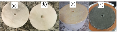
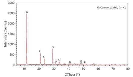
Table.1 displays the X-ray Fluorescence (XRF) outcomes, while Figure 2 depicts the X-ray diffraction (XRD) findings of the samples.
Table 1: XRF results of gypsum samples.
|
Sample Name |
CaO |
Na2O |
TiO2 |
MnO |
SO3 |
LOI* |
|
Surface rock |
32.48 |
0.096 |
0.019 |
0.006 |
45.4 |
20.88 |
LOI= loss on ignition.
The XRF analysis reveals the presence of primary element oxides, including Ca, S, and LOI, which are characteristic of gypsum. Additionally, the XRD results verify that gypsum is the main crystalline component, confirming the use of pure gypsum in this study. Figure-2 represents the XRD analysis of the samples.
2.2 Acrylic polymer liquid
In this study, an emulsion acrylic polymer was mixed with Type II Portland cement and an aluminium sulfate accelerator (1.2 M) in different weight ratios: (Acrylic: Cement: Al₂(SO₄)₃ = 5:0.5:0.5, 5:0.75:0.5, 5:1:0.5, and 5:1.5:0.5). The cement content was varied while keeping the polymer weight and aluminium sulfate quantities constant. The aluminium sulfate ratio of 0.5 (1.2 M) was chosen to prevent excessive reductions in the cement fluidity. Table.2 presents the physical and chemical specifications of the liquid polymer.
2.3 Polyurethane (PU)
Hhydrophobic foam (Seal Boss 1510) made from diphenylmethane diisocyanate (MDI) polyurethane was utilized. The gelling time was controlled by incorporating a 15x accelerator. Table 2 provides the physical and chemical specifications of the polyurethane (PU).
The foam reaction is influenced by the amount of accelerator used. Higher percentages of accelerator result in heightened reactivity, shorter gelling time, greater expansion, and reduced density.
Table 2. Physical and chemical specifications of the acrylic and polyurethane components.
|
Property |
Acrylic |
Seal Boss1510 |
Accelerator |
|
Appearance |
Milky |
Amber |
Clear |
|
Density, g/cm3 |
0.99 |
1.12 |
0.93 |
|
Viscosity, cps |
3.0 |
160-250 |
20.0 |
|
Solubility in water |
Dilutable |
Not |
Not |
2.4 Sample Treatment
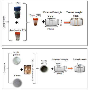
Figure 3 depicts the schematic composition of both polyurethane and acrylic polymer liquid materials. In the acrylic polymer liquid process, a specific amount of acrylic polymer is initially mixed with various cement proportions, designated as (ARC 5:0.5, ARC 5:0.75, ARC 5:1, and ARC 5:1.5). Afterward, a constant amount of aluminium sulfate is added to the mixture of cement and acrylic polymer. For the polyurethane application, a compound with a 5% accelerator ratio is utilized. The materials are poured in four layers, with a total thickness of 2 mm covering the surface and wall of the axial hole of the samples. A total of five treated samples were employed in this study.
2.5 Dissolution test
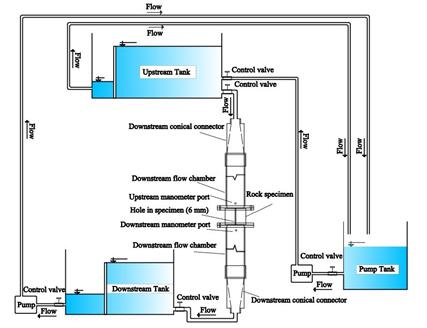
The experimental setup used in this study is designed to simulate dissolution tests under low-pressure conditions. Figure 4 depicts the schematic of the dissolution testing apparatus, which consists of two primary components: the water supply and control system, and the test cell. The water supply and control system includes a pump, a pump tank, an upstream tank with adjustable height, a downstream tank with fixed height, and a downstream pump. The test cell is composed of three sections: an upstream flow chamber, a central cell, and a downstream flow chamber. The test begins with the pump moving 100 liters of water from the pump tank to the upstream tank. By opening the upstream tank valve, water flows into the test cell, with any excess returning to the pump tank. Within the test cell, water passes through the axial hole into the downstream tank, gradually enlarging the hole diameter (in untreated samples). The water collected in the downstream tank is measured and recirculate to the pump tank using the downstream pump. Manometers installed in the upstream and downstream flow chambers monitor pressure values throughout the test.
2.6 Other tests
Electrical conductivity (EC) of the water samples was measured using ATC (Automatic Temperature Compensation) equipped device.
To measure the dissolved gypsum content in the water samples, the EDTA titration method proposed by [20] was used. In this procedure, 50 ml of the water sample was measured with a pipette and poured into a clean conical flask. Then, 10 ml of a buffer (1 M NH4OH) solution was added to the flask to reach a pH of 10-11, followed by the addition of a Eriochrome Black T indicator. The titration began with the gradual addition of the standardized EDTA (0.01 M Ethylenediaminetetraacetic acid) solution from a burette to the sample solution in the conical flask. The titration reached its endpoint as the solution changed color from red to blue, indicating the reaction between EDTA and calcium ions. The recorded EDTA volume was utilized to calculate the quantity of dissolved calcium using Eq.1. To improve result accuracy, the test was iterated three times, and the mean of the finds was taken.
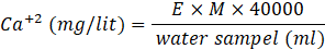
Where, E is the volume of EDTA and M is the molarity of EDTA (0.01).
3. Results and Discussion
3.1 Untreated Samples
The solubility tests on untreated gypsum rock as depicted in Figure 5, revealed that increasing the applied pressure significantly influences flow rates and the final hole diameters. For the sample subjected to a constant pressure of ΔH = 40 cm, the flow rate increased from 3.3 L/min to 5.9 L/min over a testing period of 15,300 seconds, resulting in an average final hole diameter of 9 mm.
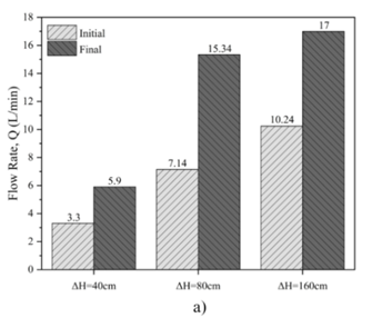
When the pressure was raised to ΔH = 80 cm, the flow rate showed a more substantial increase, rising from 7.14 L/min to 15.34 L/min during the same duration. This condition produced an average final hole diameter of 10.5 mm.
Under the highest constant pressure of ΔH = 160 cm, the flow rate exhibited the most significant rise, increasing from 10.24 L/min to 17 L/min within 15,300 seconds. This condition resulted in an average final hole diameter of 13.5 mm.
The dissolution test results, summarized in Table 3, indicate a clear trend; higher upstream pressures enhance the solubility of gypsum rock. This enhancement is evidenced by the increased flow rates and larger hole diameters. The findings underscore that as pressure increases the dissolution rate accelerates, which can be attributed to the pressure effect on reducing the chemical potential barrier for gypsum dissolution in the fluid.
Table 3. Solubility test of the untreated samples under different head pressure.
|
ΔH (cm) |
Q (L/min) |
φ(mm) |
||
|
Initial |
Final |
Initial |
Final |
|
|
40 |
3.3 |
5.9 |
6.0 |
9.0 |
|
80 |
7.14 |
15.34 |
6.0 |
10.5 |
|
160 |
10.24 |
17.0 |
6.0 |
13.5 |
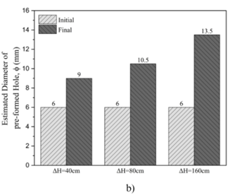
Figure 6a illustrates the relationship between changes in flow rate over time, showing a linear correlation with regression coefficients of 0.94 at ΔH = 160 cm, 0.98at ΔH = 80 cm, and 0.94 at ΔH = 40 cm. Higher pressures lead to a greater initial flow rate, reinforcing the observation that pressure significantly impacts dissolution dynamics.
Figure 6b depicts the variation in hole diameter over time, also demonstrating a linear relationship. The regression coefficients are 0.98 at ΔH = 160 cm, 0.99 at ΔH = 80 cm, and 0.97 at ΔH = 40 cm. At all pressure levels, the hole diameter exhibits an initial rapid increase, followed by a more gradual growth, with the trend becoming steeper as pressure increases.
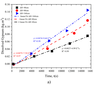
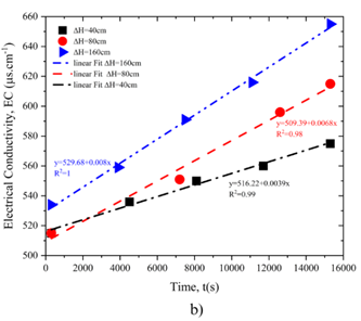
Figure 7 presents the results of titration and electrical conductivity tests. These findings reveal a gradual increase in calcium content in the water over time. As calcium concentration rises, water conductivity increases proportionally. Under ΔH = 160 cm, the calcium concentration is notably higher than in samples subjected to lower pressures, indicating enhanced solubility under higher pressure. This is consistent with the larger hole diameter observed under ΔH = 160 cm, as reported in the solubility test results.
The electrical conductivity data further validate the link between pressure and solubility, demonstrating that higher pressures amplify the dissolution rate. These results underscore the interplay between hydraulic pressure, dissolution kinetics, and the evolution of flow properties in gypsum-rich systems.
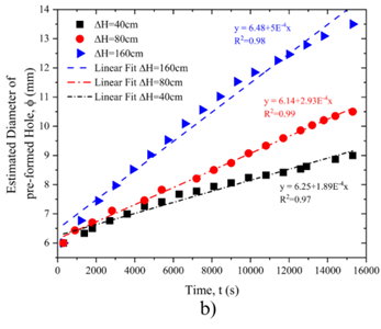
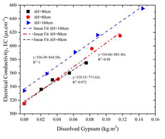
Figure 8 illustrates the direct relationship between the amount of dissolved gypsum and electrical conductivity under varying pressure levels. The data reveal a strong linear association, with regression coefficients of 1.00 at ΔH = 160 cm, 0.98 at ΔH = 80 cm, and 0.97 at ΔH = 40 cm. These results highlight electrical conductivity as a critical parameter for quantifying gypsum dissolution. The consistent linear trend across all pressures accentuates the reliability of conductivity measurements in evaluating gypsum solubility under different hydraulic conditions.
3.2 Treated Samples
Table.4 provides the dissolution test results of the treated samples.
Fig.9 presents the histogram of the results. The findings reveal that when polyurethane and acrylic are utilized with the cement ratios ARC (5:0.5), ARC (5:0.75), the flow rate remains constant at both the beginning and end of the test, resulting in no change in the hole diameter and flow rate. This can be ascribed to the high resistance of PU to hydrolysis and erosion. Additionally, it demonstrates the strong adhesion between PU and the gypsum samples. Similarly, the halting in the dissolution of the ARC-treated samples can be attributed to the presence of ARC, which acted as a thin film; and isolated the axial hole from the influence of water. However, when the ratio of cement in the mixture of ARC reached (5:1) and (5:1.5), both the flow rate and hole diameter exhibit linear increases. Specifically, as the ratio of cement to acrylic is (5:1) in ARC, the hole diameter increases from 6 mm to 6.2 mm, and the flow rate increases from 11.31 L/min to 12.06 L/min.
Table 4: Solubility test results of the treated samples.
|
Treated samples |
Q (L/min) |
φ(mm) |
||
|
Initial |
Final |
Initial |
Final |
|
|
PU (5.0% acc) |
11.3 |
11.3 |
6.0 |
6.0 |
|
ARC (5:0.5) |
11.3 |
11.3 |
6.0 |
6.0 |
|
ARC (5:0.75) |
11.3 |
11.3 |
6.0 |
6.0 |
|
ARC (5:1.0) |
11.31 |
12.06 |
6.0 |
6.2 |
|
ARC (5:1.5) |
11.29 |
12.28 |
6.0 |
6.5 |
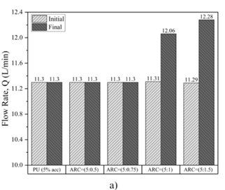
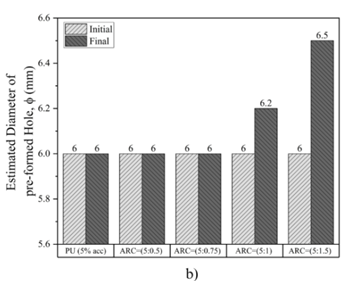
Similarly, when the ratio of cement to acrylic is (5:1.5) in ARC mixture, the hole diameter increases from 6 mm to 6.5 mm, and the flow rate increases from 11.29 L/min to 12.28 L/min. Hence, there is a greater likelihood of dissolution occurring when a higher proportion of cement is utilized. Consequently, Portland cement reduces the ability of the grout to protect the gypsum sample from dissolution
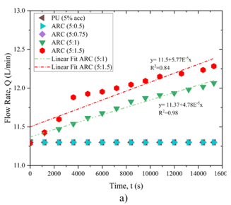
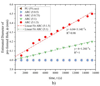
Figure10 displays the process of changes in flow rate and hole diameter over time in the treated state. The results suggest that when polyurethane and acrylic polymer are utilized with the cement ratios ARC (5:0.5) and ARC (5:0.75), the flow rate remains consistent throughout the test, leading to no variation in the hole diameter. However, when the ratio of cement in the mixture of ARC reached (5:1) and (5:1.5), both the flow rate and hole diameter exhibit linear increases. Specifically, in the case of the cement ratio (5:1) in ARC, the regression coefficient is 1 for flow rate and 0.98 for hole diameter, respectively. Similarly, for the cement ratio (5:1.5) in ARC, the regression coefficients are 0.98 and 0.84 for flow rate and hole diameter, respectively.
4.Conclusion
The aim of this study is to examine the solubility of gypsum rock and methods for treating its solubility. The findings of this investigation can be summarized as follows:
- Solubility of gypsum rock occurs even under low pressures, and its solubility increases as pressure rises.
- The consistent hole diameter maintained when employing the polyurethane treatment method indicates robust adhesion of this material to gypsum rock and its hydrophobic properties.
- The acrylic polymer treatment method shows that the hole diameter varies with increasing cement ratio. Therefore, the optimal ratio for this method can be considered as the limit ARC (5:1), effectively preventing dissolution in gypsum rock.
References
[1] M. Ezersky, L. V. Eppelbaum, and A. Legchenko, "General introduction to the karst problem," IOP Publishing Ltd, 2023. doi:10.1088/978-0-7503-3635-2ch1.
View Article
[2] K. S. Johnson, "Gypsum karst in the United States," International Journal of Speleology, vol. 25, no. 3, p. 13, 1996.
View Article
[3] P. Milanović, N. Maksimovich, O. Meshcheriakova, P. Milanović, N. Maksimovich, and O. Meshcheriakova, "Overview of dams and reservoirs in evaporites," Dams and Reservoirs in Evaporites, pp. 115-157, 2019.
View Article
[4] A. Klimchouk and V. Andrejchuk, "Environmental problems in gypsum karst terrains," International Journal of Speleology, vol. 25, no. 3, p. 11, 1996.
View Article
[5] A. A. Jeschke, K. Vosbeck, and W. Dreybrodt, "Surface controlled dissolution rates of gypsum in aqueous solutions exhibit nonlinear dissolution kinetics," Geochimica et Cosmochimica Acta, vol. 65, no. 1, pp. 27-34, 2001.
View Article
[6] D. C. Ford and P. W. Williams, Karst geomorphology and hydrology. Springer, 1989.
View Article
[7] F. Gutiérrez, M. Mozafari, D. Carbonel, R. Gómez, and E. Raeisi, "Leakage problems in dams built on evaporites. The case of La Loteta Dam (NE Spain), a reservoir in a large karstic depression generated by interstratal salt dissolution," Engineering Geology, vol. 185, pp. 139-154, 2015.
View Article
[8] N. Al-Ansari, "Mosul Dam: Is it the Most Dangerous Dam in the World?," 2020, doi: https://doi.org/10.1007/s10706-020-01355-w.
View Article
[9] K. D. Weaver and D. A. Bruce, Dam foundation grouting. ASCE press Reston, VA, 2007.
View Article
[10] L. Li, S. Li, Q. Zhang, J. Cui, Z. Xu, and Z. Li, "Experimental study of a new polymer grouting material," Chin. J. Rock Mech. Eng, vol. 29, pp. 3150-3156, 2010.
[11] P. K. Kolay, B. Dhakal, S. Kumar, and V. K. Puri, "Effect of liquid acrylic polymer on geotechnical properties of fine-grained soils," International Journal of Geosynthetics and Ground Engineering, vol. 2, pp. 1-9, 2016.
View Article
[12] C. Vipulanandan, M. B. Kazez, and S. Henning, "Pressure-temperature-volume change relationship for a hydrophilic polyurethane grout," in Grouting and deep mixing 2012, 2012, pp. 1808-1818.
View Article
[13] L. R. León and C. Matthews, "Storm water quality handbooks: construction site best management practices (BMPs) manual," 2003.
[14] F. Khelifa, Y. Habibi, and P. Dubois, "Nanocellulose-based polymeric blends for coating applications," in Multifunctional polymeric nanocomposites based on cellulosic reinforcements: Elsevier, 2016, pp. 131-175.
View Article
[15] K.-T. Chhun, S.-H. Lee, S.-A. Keo, and C.-Y. Yune, "Effect of acrylate-cement grout on the unconfined compressive strength of silty sand," KSCE Journal of Civil Engineering, vol. 23, pp. 2495-2502, 2019.
View Article
[16] M. Y. Fattah, M. M. Al-Ani, and M. T. Al-Lamy, "Studying collapse potential of gypseous soil treated by grouting," Soils and Foundations, vol. 54, no. 3, pp. 396-404, 2014.
View Article
[17] M. K. Faris, "Evaluating the Stabilization of Gypseous and Gypsiferous Sands Using Different Chemical Additives to Mitigate Gypsum Dissolution," University of South Carolina, 2020.
[18] A. Nikolaev and E. Foregina, "Protective effect of films on gypsum," Protective Films on Salts, 1944.
[19] W. Buggakupta, K. Tounchuen, W. Panpa, and S. Jinawath, "Early production of high strength and improved water resistance gypsum mortars from used plaster mould and cullet waste," Journal of Materials in Civil Engineering, vol. 32, no. 6, p. 04020116, 2020.
View Article
[20] G. Horvai, "Gary D. Christian, Purnendu (Sandy) Dasgupta and Kevin Schug: Analytical chemistry," ed: Springer, 2014.
View Article
[1] M. Ezersky, L. V. Eppelbaum, and A. Legchenko, "General introduction to the karst problem," IOP Publishing Ltd, 2023. doi:10.1088/978-0-7503-3635-2ch1. View Article
[2] K. S. Johnson, "Gypsum karst in the United States," International Journal of Speleology, vol. 25, no. 3, p. 13, 1996. View Article
[3] P. Milanović, N. Maksimovich, O. Meshcheriakova, P. Milanović, N. Maksimovich, and O. Meshcheriakova, "Overview of dams and reservoirs in evaporites," Dams and Reservoirs in Evaporites, pp. 115-157, 2019. View Article
[4] A. Klimchouk and V. Andrejchuk, "Environmental problems in gypsum karst terrains," International Journal of Speleology, vol. 25, no. 3, p. 11, 1996. View Article
[5] A. A. Jeschke, K. Vosbeck, and W. Dreybrodt, "Surface controlled dissolution rates of gypsum in aqueous solutions exhibit nonlinear dissolution kinetics," Geochimica et Cosmochimica Acta, vol. 65, no. 1, pp. 27-34, 2001. View Article
[6] D. C. Ford and P. W. Williams, Karst geomorphology and hydrology. Springer, 1989. View Article
[7] F. Gutiérrez, M. Mozafari, D. Carbonel, R. Gómez, and E. Raeisi, "Leakage problems in dams built on evaporites. The case of La Loteta Dam (NE Spain), a reservoir in a large karstic depression generated by interstratal salt dissolution," Engineering Geology, vol. 185, pp. 139-154, 2015. View Article
[8] N. Al-Ansari, "Mosul Dam: Is it the Most Dangerous Dam in the World?," 2020, doi: https://doi.org/10.1007/s10706-020-01355-w. View Article
[9] K. D. Weaver and D. A. Bruce, Dam foundation grouting. ASCE press Reston, VA, 2007. View Article
[10] L. Li, S. Li, Q. Zhang, J. Cui, Z. Xu, and Z. Li, "Experimental study of a new polymer grouting material," Chin. J. Rock Mech. Eng, vol. 29, pp. 3150-3156, 2010.
[11] P. K. Kolay, B. Dhakal, S. Kumar, and V. K. Puri, "Effect of liquid acrylic polymer on geotechnical properties of fine-grained soils," International Journal of Geosynthetics and Ground Engineering, vol. 2, pp. 1-9, 2016. View Article
[12] C. Vipulanandan, M. B. Kazez, and S. Henning, "Pressure-temperature-volume change relationship for a hydrophilic polyurethane grout," in Grouting and deep mixing 2012, 2012, pp. 1808-1818. View Article
[13] L. R. León and C. Matthews, "Storm water quality handbooks: construction site best management practices (BMPs) manual," 2003.
[14] F. Khelifa, Y. Habibi, and P. Dubois, "Nanocellulose-based polymeric blends for coating applications," in Multifunctional polymeric nanocomposites based on cellulosic reinforcements: Elsevier, 2016, pp. 131-175. View Article
[15] K.-T. Chhun, S.-H. Lee, S.-A. Keo, and C.-Y. Yune, "Effect of acrylate-cement grout on the unconfined compressive strength of silty sand," KSCE Journal of Civil Engineering, vol. 23, pp. 2495-2502, 2019. View Article
[16] M. Y. Fattah, M. M. Al-Ani, and M. T. Al-Lamy, "Studying collapse potential of gypseous soil treated by grouting," Soils and Foundations, vol. 54, no. 3, pp. 396-404, 2014. View Article
[17] M. K. Faris, "Evaluating the Stabilization of Gypseous and Gypsiferous Sands Using Different Chemical Additives to Mitigate Gypsum Dissolution," University of South Carolina, 2020.
[18] A. Nikolaev and E. Foregina, "Protective effect of films on gypsum," Protective Films on Salts, 1944.
[19] W. Buggakupta, K. Tounchuen, W. Panpa, and S. Jinawath, "Early production of high strength and improved water resistance gypsum mortars from used plaster mould and cullet waste," Journal of Materials in Civil Engineering, vol. 32, no. 6, p. 04020116, 2020. View Article
[20] G. Horvai, "Gary D. Christian, Purnendu (Sandy) Dasgupta and Kevin Schug: Analytical chemistry," ed: Springer, 2014. View Article