International Journal of Civil Infrastructure (IJCI)
ISSN: 2563-8084

Volume 8 - Year 2025- Pages 55-67
DOI: 10.11159/ijci.2025.007
Seismic Vulnerability Assessment of Urban Metro Tunnels: Influence of Material Properties and Cover Depth through Numerical Modelling
Pranav Mahajan1, BN Rao2
1Research Scholar, Structural Engineering Lab, Department of Civil Engineering,
Indian Institute of Technology Madras, Chennai, Tamil Nadu, India – 600 036
pranavmahajan096@gmail.com; ce23d018@smail.iitm.ac.in
2Professor, Structural Engineering Lab, Department of Civil
Engineering,
Indian Institute of Technology Madras, Chennai, Tamil Nadu, India – 600 036
bnrao@iitm.ac.in
Abstract - Structures constructed, either above or below the ground, are susceptible to damage by seismic vulnerabilities. In underground structures, especially tunnels, these vulnerabilities may lead to catastrophic failure causing infrastructural damage and loss of human lives. Therefore, construction of tunnels in urban regions require understanding of complex geological ground conditions for designing the underground tunnel system resistant against vulnerable seismic conditions. Studies indicate concerns in underground tunnels, during and post seismic effect, which require engineering assessment to ensure the tunnel structural safety. Hence, mechanical behaviour analysis of the tunnel lining is essential to determine the influence under varying conditions and its susceptibility to different ground motions. The current study analyses the seismic vulnerability impact on tunnel lining under variability in ground material characteristics and overburden depth. The analysis determines the ground motion impact in both x and y directions to comprehend the tunnel lining behaviour and further improve its seismic resistance. The behaviour is analysed to compare different mechanical parameters required for tunnel lining design in both the directions. To carry out this, three analytical frameworks: linear static, eigenvalue, and nonlinear time history analysis, defines the methodology utilised to simulate the seismic behaviour analysis under different scenarios. This is numerically simulated using finite element software, MIDAS GTS NX, analysing the structural sensitivity against combined variation in material characteristics and overburden depth for different seismic ground motions. The study utilises acceleration time-history plots of the Tokachi and Tohoku Coast ground motions to understand the behaviour. The analysis for different analysed cases suggests significant influence of material characteristics on maximum displacement, axial force, and bending moment compared to the seismic impact. In this, higher tunnel overburden depth leads to higher axial force and bending moment on tunnel lining depicting the influence of overburden depth. Thus, the results obtained using numerical analysis provide comprehensive behaviour of the tunnel lining, which can be utilised by designers for enhancing the seismic resistance.
Keywords: Soil-structure interaction, Seismic analysis, Numerical modelling, MIDAS GTS NX, Non-linear time history analysis
© Copyright 2025 Authors - This is an Open Access article published under the Creative Commons Attribution License terms. Unrestricted use, distribution, and reproduction in any medium are permitted, provided the original work is properly cited.
Date Received: 2025-01-17
Date Revised: 2025-05-16
Date Accepted: 2025-06-18
Date Published: 2025-06-30
1. Introduction
Underground metro tunnels necessitate seismic design consideration in areas subjected to periodic earthquakes of high magnitude and under high seismic risk zones. These underground structures must utilise seismic-resistant methods to avoid structural damage in high-risk zones. Providing flexible connections, seismic isolators, and real-time instrumentation supports in detecting and mitigating damage caused by such events [1], [2]. On comparison, tunnels with low overburden are more prone to seismic effects than tunnels with high overburden [3]–[5]. Numerous experimental and numerical studies have been carried out to analyse the seismic effects on different tunnel components. Detailed geological investigation and safety equipment requirement is essential to decrease earthquake effect on underground structures, leading to reduced damage and more operational service life. Various experimental [6], [7], numerical [8]–[11], and analytical [12], [13] studies determined the tunnel behaviour under ground motion. Owen and Scholl [14] determined the tunnel deformation mode, which includes axial deformation, ovaling, racking and rocking. Cilingir and Madabhushi [12], [15] analysed the dry sand tunnel behaviour using centrifuge experiments to understand the soil entry effects under seismic conditions .
In the Indian subcontinent, the Himalayan belt witnessed major seismic happenings i.e. the Kashmir earthquake (Mw 7.6) and the Gorkha earthquake in 2015 (Mw 7.8) [16], [17]. India’s national capital, Delhi, has observed tremors repeatedly due to these earthquakes. With rapid urbanisation, Delhi has great infrastructural projects to be constructed having national importance. Delhi metro network is one such spider web spread over the whole region, and increasing its limits day by day. The occurrence of any earthquake within the metro zone limits aids as a cautioning to study the underground metro tunnel strength and damage resistance. Therefore, understanding of the tunnel lining behaviour subjected to different seismic conditions is essential for varying material characteristics and overburden depth. This is carried out to understand the mechanical behaviour of tunnel lining under different analysed cases. Hence, the current study involves analysis of tunnel lining system under different seismic conditions in both x and y directions to determine seismic design requirements of the concrete tunnel lining and prevent catastrophic design failure.
In this study, numerical modelling of the dynamic behaviour of underground tunnels is analysed subjected to different seismic ground motions. Herein, material characteristics of the Delhi metro system [18] are considered for reference. This provides an inference to the geological conditions in the urban transportation system. The numerical analysis comprehends tunnel-soil system and concrete lining subjected to multiple seismic ground motions in different directions under varying material characteristics and overburden depth. It is observed that the material characteristics have great influence on the mechanical behaviour of tunnel lining compared to the seismic ground motion effect. In contrast, seismic ground motions influence structural behavioural characteristics of tunnel lining than material characteristics. So, both parameters affecting the tunnel system are critical for the seismic analysis. Out of two, material characteristics have a deterministic impact, while overburden depth has a non-deterministic impact due to its reliance over the magnitude of seismic effect. Therefore, the results obtained in this study will help in the seismic design of other metro tunnels under coherent seismic conditions worldwide.
2. Numerical modelling
Design of underground tunnels is challenging in regions susceptible to high seismic activities [18]. Research in the lower Himalayan region [19] subjected to the Uttarkashi earthquake, 1991 and seismic behaviour in liquefiable deposits [20] indicates good understanding of the tunnel dynamics and response under seismic effects. Research studies have employed numerous methodologies to understand the tunnel behaviour in seismic conditions. Numerical analysis of such conditions provides an in-depth analysis of the structural behaviour of tunnel lining system.
In current study, 3D soil-structure model is utilised to simulate the behaviour of the tunnel system. Numerical simulation is utilised using finite element software, MIDAS GTS NX, to analyse the dynamic behaviour of the tunnel lining under different seismic conditions. Further, the study aims to determine the impact of analysed parameters and understand the tunnel response under different seismic conditions. Numerical methodology involving geometric modelling, element type selection, loading and boundary condition application, and constitutive material model selection is described in the subsequent sections.
2.1. Geometry modelling
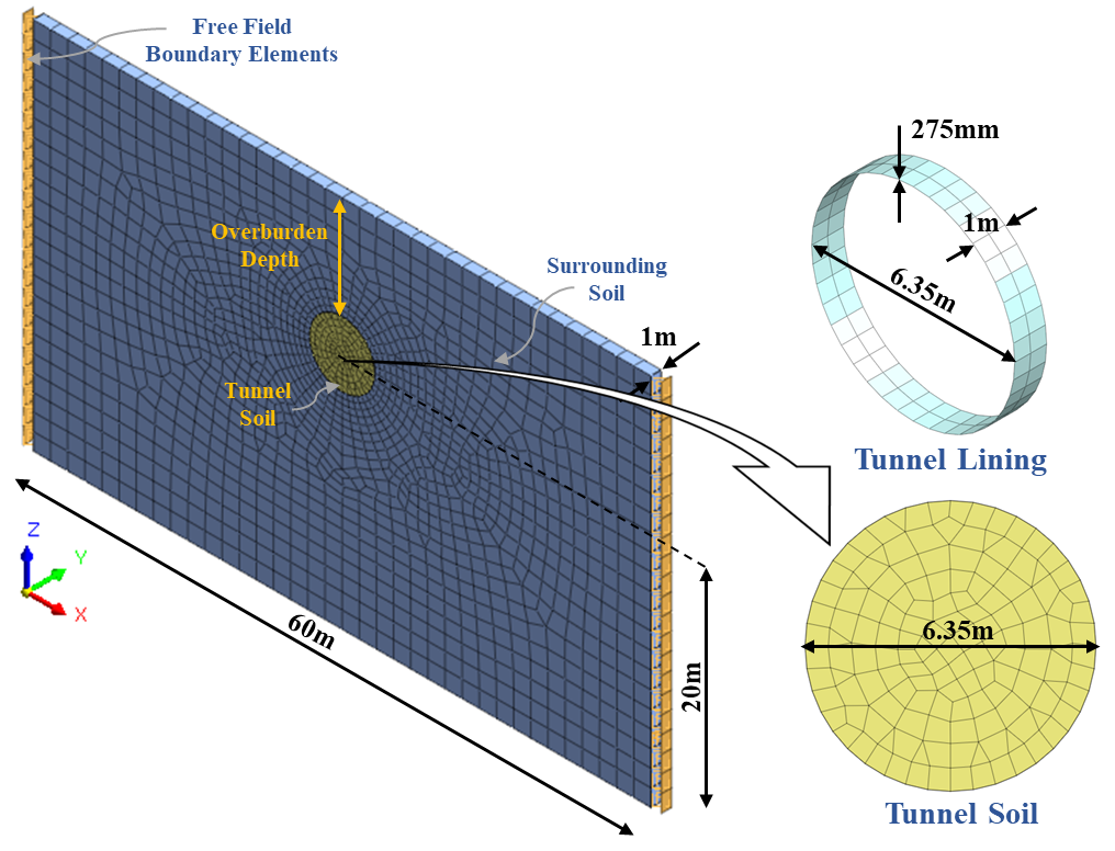
The geometry modelling of circular tunnel section with diameter measuring 6.35 m and 275 mm lining thickness (T1) is developed numerically. In this, the material property for concrete tunnel lining is assumed as elastic-isotropic. The surrounding soil is assumed as homogeneous and isotropic. The soil surrounding the concrete tunnel section is modelled for two different overburden depths, 10 m and 20 m. Therefore, two geometric models of dimensions 60 × 1 × 36.35 m and 60 × 1 × 46.35 m in x, y, and z directions, respectively, are established. Two different types of surrounding soil - highly weathered quartzite (R1) and loose sand (R3) - utilising the Mohr-Coulomb failure criterion, are considered for the constitutive modelling. Table 1 describes the material characteristics of the surrounding soil and tunnel lining employed for numerical modelling. The material properties utilised in the study are obtained from the technical investigation report by the Delhi Metro.
Figure 1 illustrates the 3D finite element model (FEM) comprising hybrid mesh elements for modelling the surrounding soil elements. 2D shell mesh elements with uniform thickness are extracted for tunnel concrete lining. The finite element software, MIDAS GTS NX, is used to develop the tunnel numerical model for evaluating the soil-structure interaction under seismic conditions. To remove duplicate interaction faces and fuse the different geometry parts, the Boolean auto-connect feature is utilised.
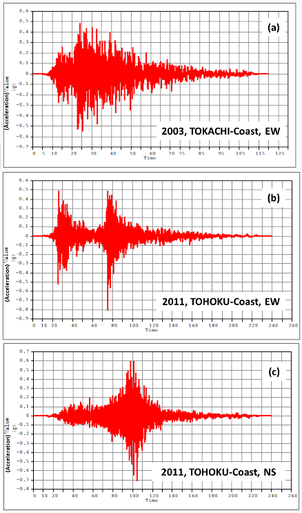
Table 1. Properties of materials utilised
|
Description |
Highly weathered quartzite (R1) |
Loose Sand (R3) |
Lining (T1) |
|
Unit Weight (γ) (kN/m3) |
25 |
19 |
24 |
|
Poisson’s Ratio (ν) |
0.3 |
0.25 |
0.2 |
|
Elastic Modulus (E) (MPa) |
200 |
60 |
31600 |
|
Cohesion (c) (kPa) |
15 |
10 |
- |
|
Friction Angle (φ) (degree) |
31 |
30 |
- |
|
Damping Ratio (%) |
5 |
5 |
5 |
|
Description |
Represented as |
Moment Magnitude (Mw) |
Year |
PGA (g) |
|
Tokachi-Coast, EW |
H24_T1-I-1 |
8.3 |
2003 |
0.5484 |
|
Tohoku-Coast, EW |
H24_T1-I-2 |
9.1 |
2011 |
0.8105 |
|
Tohoku-Coast, NS |
H24_T1-I-3 |
9.0 |
2011 |
0.7065 |
2.2. Seismic loading
Three acceleration time-history datasets, selected from MIDAS database, are used as input ground motions for tunnel models under different conditions. The details of these datasets are tabulated in Table 2. The selected datasets act as input for the non-linear time history (NLTH) analysis of the soil-tunnel system to analyse the dynamic response under different seismic ground motions. Acceleration time history plots for the three input ground motions are provided in Figure 2. These datasets are applied in transverse and longitudinal directions about the tunnel longitudinal axis. In other words, this data is provided in both x and y directions to compare the variation in dynamic response of the soil-tunnel system under different analysed parameters.
During simulation, the insitu stage is analysed for geostatic behaviour causing ovaling in the tunnel concrete lining. Further, full ground acceleration is provided to the soil-tunnel system to analyse the maximum seismic effect under NLTH analysis.
2.3. Boundary constraints
Analysis of tunnel lining subjected to seismic motions require free-field boundary conditions at the vertical faces of the soil-tunnel model. The free-field boundary condition provides a semi-infinite medium for the seismic wave to travel within the system. However, it is noted that the normal constraint utilisation on all the vertical faces cause reflection of the seismic wave from the tunnel boundary. This leads to additional force and stress on the tunnel lining, which contradicts the actual site condition behaviour. At the model bottom, a fixed boundary restraint is provided representing a rigid base system.
3. Seismic analysis
For the current study, the methodology convoluted in seismic analysis is characterised into six categories: (1) 3D numerical model creation, including material, loading and boundary characteristics, (2) Linear static analysis, utilising the self-weight loading, (3) Eigenvalue analysis, (4) NLTH analysis, for different ground motion datasets considered, (5) Analysis of results, for maximum displacements, axial forces and bending moments, and (6) Sensitivity of the obtained data. The diagram illustrating the methodology involved is described in Figure 3. The sensitivity analysis is carried out for two factors - material characteristics and tunnel overburden depth. This framework, comprising six steps, is utilised to comprehensively evaluate the seismic behaviour and its influence on the tunnel lining. The analysis under varying parameters provides the determinacy and impact for different seismic conditions over the tunnel lining.
Linear static analysis provides the deformation behaviour of the surrounding soil and tunnel lining subjected to self-weight. To carry out dynamic analysis, eigenvalue analysis is executed to determine the natural frequencies, time period and mode shapes of the soil-tunnel system. The analysis captures the value of the percentage of modal mass in direction to which ground acceleration is provided. In this, the first two maximum values of percentage of modal mass corresponds to natural frequencies or time periods utilised as input for the NLTH analysis. In NLTH analysis, results obtained for tunnel lining is used to determine its mechanical behaviour under varying parameters subjected to seismic effects.
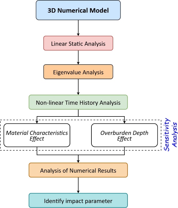
For the eigenvalue analysis, 50 mode shapes are obtained in each analysis. The two mode shapes corresponding to the first two maximum percentage of modal mass are used as input in NLTH analysis. In NLTH analysis, a time step of 0.02 s for a total time period of 10 s is utilised. This has generated 500 steps for analysis under the corresponding seismic response in the particular direction. Maximum ground and tunnel crown displacement, bending moment and axial force under two different material characteristics and overburden depths subjected to three different ground motions, are analysed to determine their behaviour and impact for the studied cases.
4. Discussions
4.1. Linear static analysis
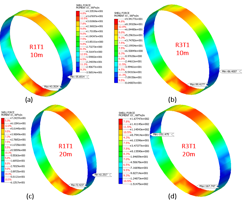
The structural behaviour of the soil-tunnel system under self-weight load is analysed using linear static analysis to understand the effect of material characteristics and the overburden depth over tunnel lining. The analysis includes determining maximum axial force and bending moment in static analysis. The results obtained for each analysed case are summarised in Tables 3 and 4. Results indicate decrease in axial forces values by 10.29% and increase in bending moment values by 129.31% when material characteristics varies from R1 to R3. The results obtained depicts the vital impact of surrounding soil material characteristics on the tunnel lining behaviour in the insitu static analysis. Further, with increase in overburden depth from 10 m to 20 m, both axial force and bending moment demonstrates increase in the corresponding obtained values. For the R1 case, the values obtained for axial force and bending moment are increased by 75.70% and 67.05%, respectively. While, the values are increased by 75.71% and 68.73%, respectively, for the R2 case.
Table 3. Linear static tunnel behaviour under material characteristics effect
|
Material Property Effect |
||
|
Maximum Linear Static Response |
Material Type |
|
|
R1T1/10m |
R3T1/10m |
|
|
Axial Force (kN/m) |
-1182.72 |
-1061.04 |
|
Bending Moment (kNm/m) |
43.3534 |
99.4177 |
Table 4. Linear static tunnel behaviour under overburden depth effect
|
Overburden Effect |
||||
|
Maximum Linear Static Response |
Material Type/Tunnel Depth |
|||
|
R1T1/10m |
R1T1/20m |
R3T1/10m |
R3T1/20m |
|
|
Axial Force (kN/m) |
-1182.72 |
-2078.08 |
-1061.04 |
-1864.34 |
|
Bending Moment (kNm/m) |
43.3534 |
72.4237 |
99.4177 |
167.747 |
The results showed the significant impact of overburden depth on the tunnel lining response, defining a correlation between the increased axial forces and bending moment with increasing overburden depth. The contour diagrams for the axial force and bending moment of different analysed cases under linear static analysis are illustrated in Figures 4 and 5, respectively.
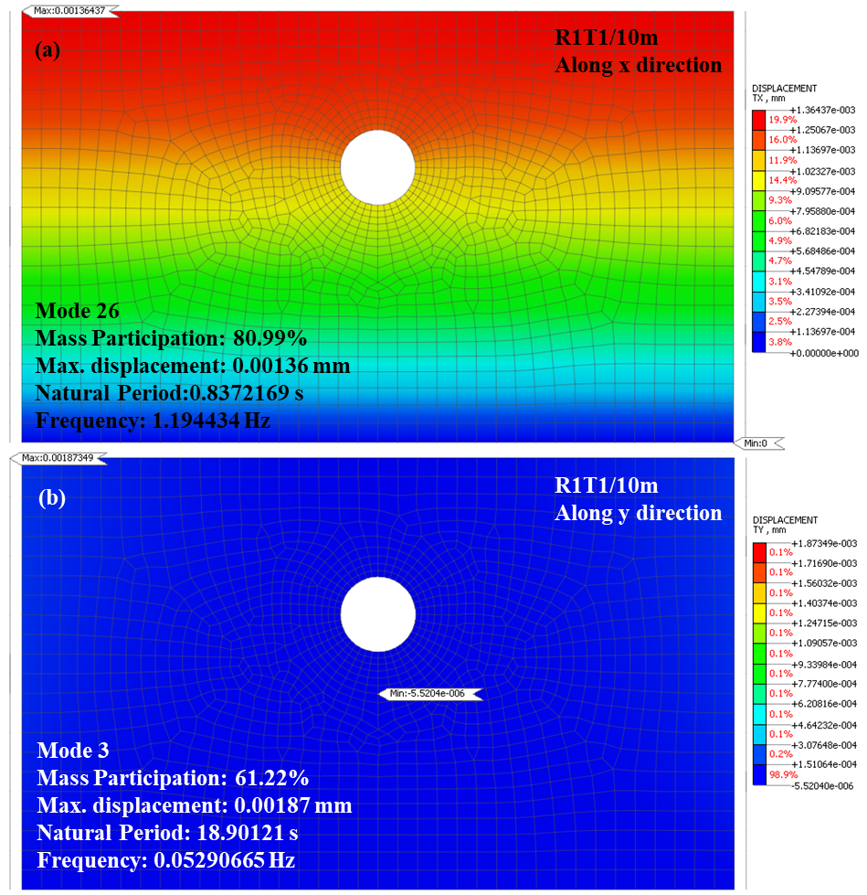
4.2. Eigenvalue analysis
After simulating the linear static behaviour, eigenvalue analysis is initiated to analyse the dynamic behaviour of the soil-tunnel system. This analysis defines the natural frequencies and mode shapes of different models under varying materials properties and overburden depth. In this, the Lanczos algorithm is employed to simulate the eigenvalue analysis of the soil-tunnel system. The algorithm is conceptualised upon the power iteration method, which provides natural frequencies and mode shapes using the assumed mode shape in the first iteration. The exact value of natural frequency and mode shape is obtained when the iteration converges.
Table 5. Eigenvalue analysis for seismic ground motion in the x-direction
|
Along the x-direction |
||||||
|
Parameter Considered |
Material |
Lining Thickness |
Overburden (m) |
Eigenvalue Analysis |
||
|
Mode No. |
Cycles |
Natural period (s) |
||||
|
Material Property Effect |
R1 |
T1 |
10 |
26 |
1.194434 |
0.8372169 |
|
75 |
3.577214 |
0.2795472 |
||||
|
R3 |
T1 |
10 |
28 |
0.7653014 |
1.306675 |
|
|
76 |
2.292004 |
0.4362994 |
||||
|
Overburden Effect |
R1 |
T1 |
10 |
26 |
1.194434 |
0.8372169 |
|
75 |
3.577214 |
0.2795472 |
||||
|
T1 |
20 |
29 |
0.936811 |
1.067451 |
||
|
79 |
2.807485 |
0.3561906 |
||||
|
R3 |
T1 |
10 |
28 |
0.7653014 |
1.306675 |
|
|
76 |
2.292004 |
0.4362994 |
||||
|
T1 |
20 |
29 |
0.6002366 |
1.66601 |
||
|
79 |
1.798821 |
0.5559196 |
||||
Table 6. Eigenvalue analysis for seismic ground motion in the y-direction
|
Along y Direction |
||||||
|
Parameter Considered |
Material |
Lining Thickness |
Overburden (m) |
Eigenvalue Analysis |
||
|
Mode No. |
Cycles |
Natural period (s) |
||||
|
Material Property Effect |
R1 |
T1 |
10 |
3 |
0.05290665 |
18.90121 |
|
9 |
0.3289339 |
3.040125 |
||||
|
R3 |
T1 |
10 |
3 |
0.03251216 |
30.75773 |
|
|
9 |
0.202223 |
4.945036 |
||||
|
Overburden Effect |
R1 |
T1 |
10 |
3 |
0.05290665 |
18.90121 |
|
9 |
0.3289339 |
3.040125 |
||||
|
T1 |
20 |
3 |
0.03259049 |
30.6838 |
||
|
9 |
0.2032394 |
4.920306 |
||||
|
R3 |
T1 |
10 |
3 |
0.03251216 |
30.75773 |
|
|
9 |
0.202223 |
4.945036 |
||||
|
T1 |
20 |
3 |
0.02002835 |
49.92923 |
||
|
9 |
0.1249332 |
8.004279 |
||||
To determine the seismic impact on the tunnel lining characteristics, seismic effect of the soil-tunnel system is analysed in both x and y directions. The eigenvalues obtained under different material characteristics and overburden depth in both x and y-direction are tabulated in Tables 5 and 6, respectively. These eigenvalues are considered as input for NLTH analysis. These mode shapes selected for the NLTH analysis are considered using the maximum percentage of modal mass. This modal mass percentage cumulates to more than 90% for the two modes considered for the NLTH analysis in each analysed case.
The model provides better accuracy with 90% modal mass considered for dynamic response. The eigenvalue analysis explained the influence of material characteristics and overburden depth on the dynamic behaviour of tunnel structure. A representative case of mode shapes for R1T1 tunnel with 10 m overburden depth in both x and y directions is illustrated in Figure 6. The figure indicates that the maximum displacement in the soil-tunnel system ranges between 0.0014 mm and 0.0019 mm. Further, the corresponding natural frequencies obtained for the two selected modes in eigenvalue analysis is used as input in NLTH analysis.
4.3. Non-linear time history analysis
After completing the insitu static analysis and eigenvalue analysis, NLTH analysis is instigated for three different seismic ground motions. The seismic ground motion details are delineated in Table 2. This analysis is commenced for varying (1) material characteristics and (2) overburden depth. The results attained define the maximum surface and crown vertical displacement, axial force, and bending moment for different analysed cases. All the analysed cases are compared under varying parameters and seismic ground motion in both the x and y-directions. These results provide mechanical behaviour of tunnel lining under varying material characteristics and overburden depth for all the analysed cases in the subsequent sections.
4.3.1. Surface and tunnel crown displacement
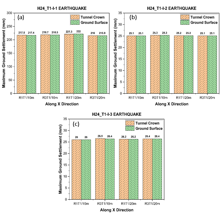
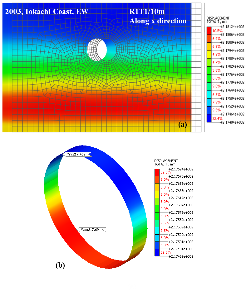
In this section, the ground surface and tunnel crown displacement is analysed in the transverse direction of the tunnel section under three seismic ground motions. The analysis is simulated under varying material characteristics (R1, R3) and overburden depths (10 m, 20 m) in both x and y directions. In the x-direction, the H24_T1-I-1 earthquake causes maximum ground displacement ranging between 215-222 mm. However, these displacement values lie in the range 25-27 mm for H24_T1-I-2 and H24_T1-I-3 earthquakes, as illustrated in Figure 7. Also, the displacement values observed over the tunnel crown and the ground surface are nearly equivalent. But, neither the material characteristics nor the overburden depth has significantly affected maximum displacement behaviour. Further, the variation in seismic effect represents alterations in ground displacement for different analysed cases. For the representative case, the total displacement contours subjected to H24_T1-I-1 earthquake along the x-direction are illustrated in Figure 8. In this, the soil model contour depicts maximum total displacement measuring 218.12 mm. While this maximum displacement occur over the invert of the tunnel lining with value amounting to 217.69 mm.
Along the y-direction, the maximum displacement observed on the ground surface is higher compared to tunnel crown displacement. But, the tunnel crown displacement decrease with changing material characteristics from R1 to R3 for 10 m overburden depth under the y-direction seismic ground motion. This behaviour is entirely opposite under 20 m overburden depth. Further, these displacement values increase with increasing overburden depth. The values increase by 25%, 108%, and 27% for R1T1/10m tunnel when measured at ground compared to the tunnel crown under three seismic motions considered for analysis. Figure 9 describes the maximum displacements for three different seismic ground motions along the y-direction.
Therefore, the maximum displacement over the ground surface and tunnel crown is influenced by both material characteristics and overburden depth along the y-direction. On comparing the results in both directions, the maximum total displacement values for the seismic ground motion along the y-direction are comparatively lower than those along the x-direction.
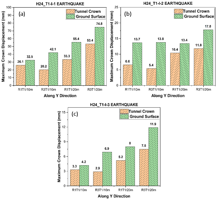
Figure 10 illustrates the deformed shape of the soil-tunnel model subjected to H24_T1-I-1 earthquake along the y-direction. The figure describes the maximum total displacement over soil and tunnel lining measuring 217.81 mm and 61.38 mm respectively. In tunnel lining, the maximum value occurs at the invert of the system. Thus, significant variation in displacement values is observed under different material characteristics and overburden depths for the analysed ground motions in both x and y directions.
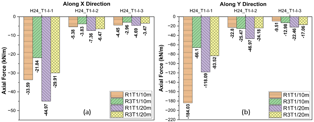
4.3.2. Axial force
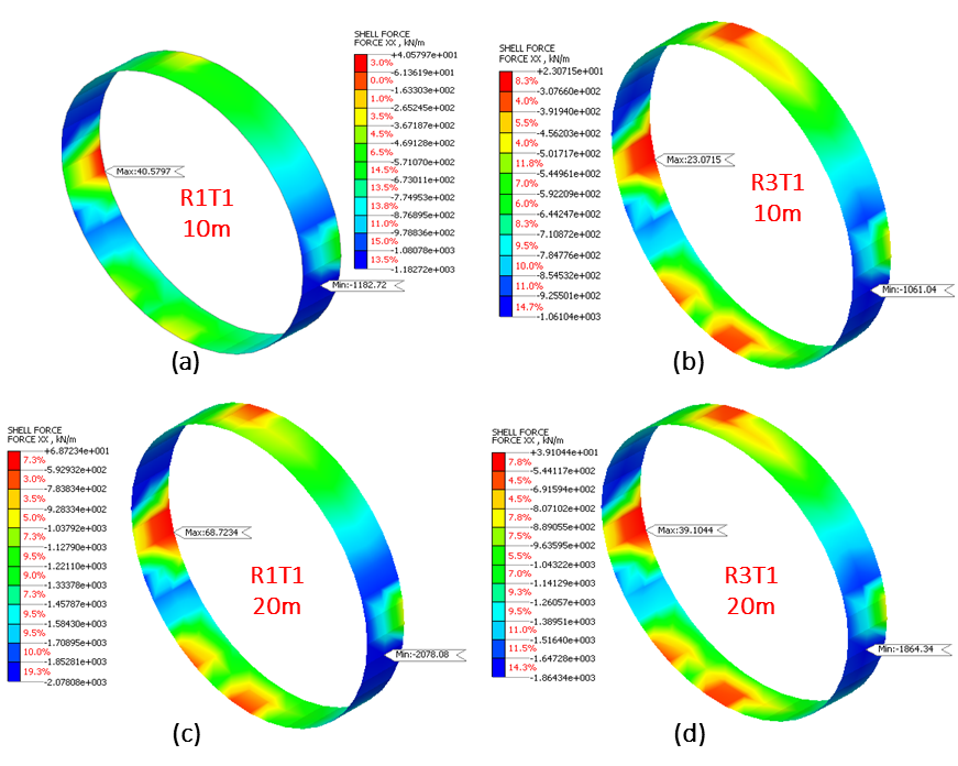
This section describes axial force variation under different material characteristics and overburden depths to analyse the effect of seismic ground motions on the tunnel lining. Upon analysis, H24_T1-I-1 earthquake provide higher axial force value, compared to other analysed seismic ground motions along x-direction. Under this earthquake, the axial force value in R1T1/10m case measures 33.59 kN. But change in material characteristics, R1T1/10m to R3T1/10m, leads to axial force measuring 44.97 kN, which is 34% higher than the former. The higher axial force value indicates the material characteristics influence on the axial force behaviour of the tunnel lining. Further, an increase in overburden depth causes decrease in the induced axial force by 34-37 % under the same material characteristics.
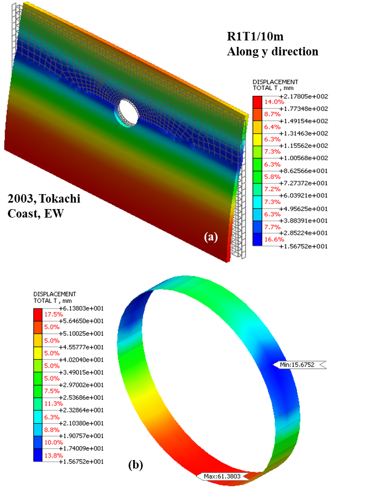
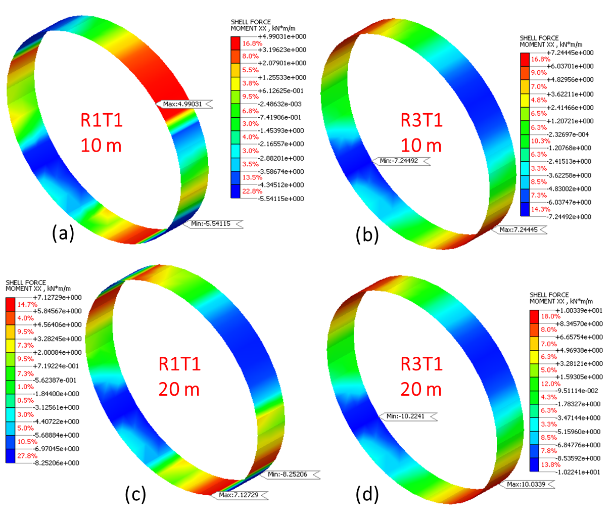
Figure 11 denotes the representative case for axial force induced in the tunnel lining under NLTH analysis subjected to H24-T1-I-1 earthquake along the x-direction. The contour profiles illustrate the maximum axial force value and their corresponding location on the tunnel lining. These profiles indicate a decrease in axial force by 34-37 % with the increase in overburden depth. However, when the surrounding material characteristics change from R1 to R3, the axial force values increase by 33-35 %. The obtained results indicate equivalent influence of both material characteristics and overburden depth on the axial force behaviour of tunnel lining under different seismic ground motions along the x-direction.
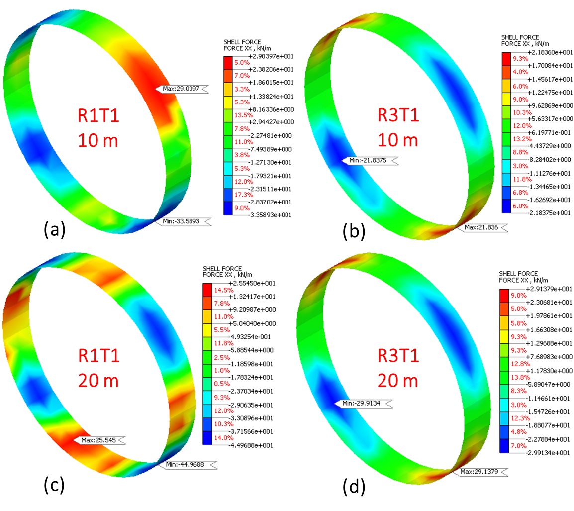
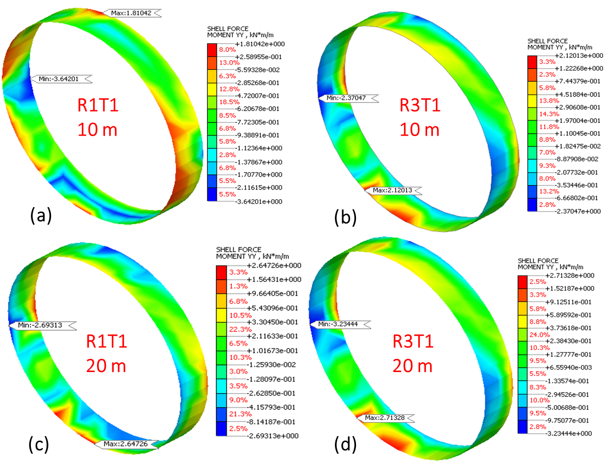
Along the y-direction, the maximum axial force values increase by 64% and 29% at overburden depths of 10 m and 20 m, respectively, when material properties change from R1 to R3 under same overburden depth. These values depict an increase by 36% and decrease by 26% for the R1 and R3 material, respectively, upon changing the overburden depth from 10 m to 20 m. Figure 12 illustrates the representative case for the maximum axial force subjected to H24-T1-I-1 earthquake along the y-direction. However, the axial force values obtained along the y-direction are higher compared to the x-direction. This behaviour represents the influence of material characteristics over overburden depth along the y-direction under different analysed seismic ground motions. The values obtained under different material characteristics and overburden depth in both x and y-directions are depicted in Figure 13. The values varies for different earthquakes analysed in the current study.
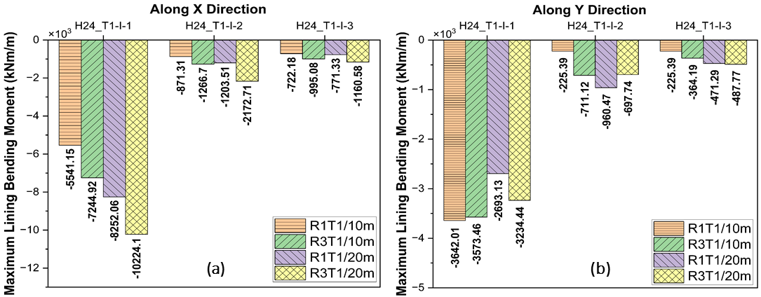
4.3.3. Bending moment
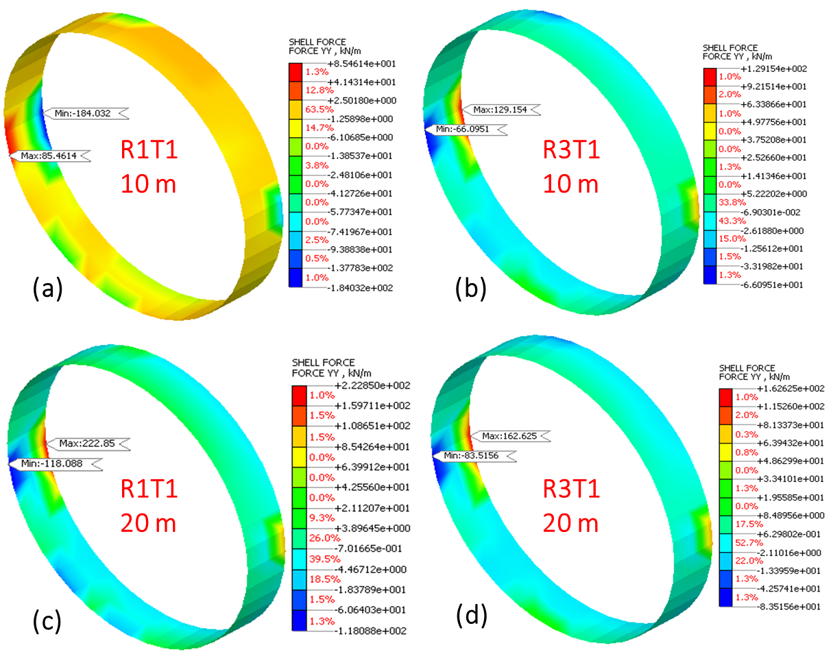
Both bending moment and axial force define the mechanical behaviour characteristics of the tunnel lining. The bending moment values increase for the H24_T1-I-1 earthquake as material characteristics change from R1 to R3 along the x-direction. The bending moment increases with increase in overburden depth from 10 m to 20 m under the same material characteristics. The maximum bending moment contour diagram, provided in Figure 14, indicates the contours for varying material characteristics and overburden depth subjected to H24_T1-I-1 earthquake along the x-direction. For the representative case, the percentage increase in bending moment measuring 31% and 41% is observed for material characteristics and overburden depth variation respectively.
Along the x-direction, the results indicate increase in bending moment by 41-49 % with an increase in overburden depth under same material characteristics. Under varying material characteristics from R1 to R3, the maximum bending moment increases by 24-31 % under constant overburden depth. This depicts the influence of overburden depth over material characteristics variation on the bending moment behaviour of tunnel lining under different seismic ground motions along the x-direction.
Also, the bending moment along the y-direction varies with the different considered seismic ground motion for the analysis. In H24_T1-I-1 earthquake, bending moment values decrease with change in both the material characteristics and overburden depth. In this case, increase in overburden depth leads to decrease in bending moment by 26% and 10% for the R1 and R3 material characteristics variation respectively. But, the value decreases by 2% and 10% on varying material characteristics from R1 to R3 under 10 m and 20 m overburden depth respectively. This behaviour is illustrated in Figure 15, depicting the maximum bending moment contours for the different seismic ground motions along the y-direction. The results obtained depicts the seismic ground motion influence along the y-direction compared to material characteristics and overburden depth variation on the bending moment behaviour of tunnel lining. Figure 16 further describes the bending moment values obtained for different analysed cases along both x and y directions.
5. Results
This study analyses the mechanical behaviour of the tunnel lining under varying parameters subjected to different seismic ground motions. For this, numerical models are simulated under different material characteristics and overburden depths to determine their influence on the mechanical behaviour of tunnel lining. The results obtained provided the following findings:
5.1. Material property effect
Material properties do not significantly affect the displacement characteristics of ground surface and tunnel crown. But, the displacement behaviour is influenced by the seismic ground motion along the x-direction. However, the displacement characteristics varies by changes in both material characteristics and seismic ground motion along the y-direction. Also, the axial force along x-direction is equally impacted by variation in material characteristics and overburden depth. In the y-direction, axial force behaviour is influenced more by material characteristics than the overburden depth. Further, bending moment is least affected by material characteristics in both x and y directions. Therefore, the material stiffness of tunnel lining is required to be analysed during design to minimise the deformations and increase resistance against seismic effects.
5.2. Overburden depth effect
The seismic effect established more impact than the overburden depth over the displacement characteristics of the soil-tunnel system along the x-direction. Along the y-direction, both overburden depth and material characteristics influence the displacements of the soil-tunnel system. As discussed above, axial force is equally influenced by overburden depth and material characteristics variation along x-direction. However, along the y-direction, overburden depth has less influence on the axial force behaviour compared to material characteristics. Further, bending moment is significantly affected by overburden depth along x-direction. Along y-direction, seismic ground motion causes more influence in affecting the bending moment behaviour of tunnel lining. Therefore, tunnels constructed in high seismic zones should consider the optimum depth to reduce the seismic effect and overburden depth influence on the mechanical behaviour.
Hence, the impact consideration of both parameters is essential while designing the tunnel lining subjected to seismic events in both the directions. The pivotal influence of surrounding soil and tunnel lining material properties is more significant than the geometrical effects. Thus, the current study provided the analysis of the soil-tunnel system under different seismic ground motions and further determined the impact of various material characteristics and overburden depths in both x and y directions, which helps in designing the tunnels for seismic resistance. This preserves the structural integrity during any seismic events occurrence.
6. Conclusions
The effect of material properties and overburden depth is assessed for the comprehensive seismic vulnerability assessment of urban metro tunnels utilising numerical simulation. Axial force and bending moment in tunnel linings were found to be significantly influenced by material characteristics through linear static, eigenvalue, and nonlinear time history analyses under various seismic ground motions. The effect on displacement was more evident in the y-direction. The effect of overburden depth on displacement was less consistent, but it leads to increase in axial forces and bending moments. The seismic response was different in the x and y directions, with the x-direction usually depicting higher displacements and the y-direction providing high sensitivity for axial forces and bending moment. Out of all the seismic events analysed, the Tokachi-coast seismic ground motion provided the most extensive structural response. The results obtained highlights the importance of considering both material stiffness and optimum overburden depth in the design of tunnels, particularly in areas where high seismic activity is common, to realize structural performance and sustainability during earthquakes.
Acknowledgements: The first author would like to acknowledge the funding support provided by Prime Minister’s Research Fellowship (2503524), Indian Institute of Technology Madras, and the Ministry of Education (MoE), and Government of India for the research grant on the Doctoral Degree during research.
References
[1] K. Aziz, R. A. Mir, and A. Ansari, "Precision modeling of slope stability for optimal landslide risk mitigation in Ramban road cut slopes, Jammu and Kashmir (J&K) India," Model. Earth Syst. Environ., vol. 10, no. 3, pp. 3101-3117, 2024, doi: 10.1007/s40808-023-01949-2. View Article
[2] J. Ciurlanti, S. Bianchi, and S. Pampanin, Raising the bar in seismic design: cost-benefit analysis of alternative design methodologies and earthquake-resistant technologies, vol. 21, no. 5. Springer Netherlands, 2023. doi: 10.1007/s10518-023-01625-x.
View Article
[3] J. He, W. Chen, W. Zhao, S. Huang, and Y. Yao, "Numerical test on polystyrene tunnel seismic-isolation material," Polish J. Chem. Technol., vol. 18, no. 3, pp. 122-127, 2016, doi: 10.1515/pjct-2016-0058.
View Article
[4] D. Xu,H.; Li, T.; Xia, L.; Zhao, J.X.; Wang, "Shaking table tests on seismic measures of a model mountain tunnel," Tunn. Undergr. Sp. Technol, no. 60, pp. 197-209, 2016.
View Article
[5] Fang, Qin Han. Fracture prevention of steel bridges [a]. Proceedings of the ninth annual meeting of the Chinese society of civil engineering [C]. Beijing: China Water Conservancy and Hydropower Press, 2000.5:126-131 View Article
[6] M. Patil, D. Choudhury, P. G. Ranjith, and J. Zhao, "A Numerical Study on Effects of Dynamic Input Motion on Response of Tunnel-Soil System," 16th World Conf. Earthq. Eng., pp. 1-10, 2017.
View Article
[7] G. Tsinidis, E. Rovithis, K. Pitilakis, and J. L. Chazelas, "Seismic response of box-type tunnels in soft soil: Experimental and numerical investigation," Tunn. Undergr. Sp. Technol., vol. 59, pp. 199-214, 2016, doi: 10.1016/j.tust.2016.07.008.
View Article
[8] A. Bobet, "Drained and undrained response of deep tunnels subjected to far-field shear loading," Tunn. Undergr. Sp. Technol., vol. 25, no. 1, pp. 21-31, 2010, doi: 10.1016/j.tust.2009.08.001.
View Article
[9] X. Yuanliang, Z. Chao, C. Chun, and Z. Yamei, "Effect of superabsorbent polymer on the foam-stability of foamed concrete," Cem. Concr. Compos., vol. 127, no. July 2021, p. 104398, 2022, doi: 10.1016/j.cemconcomp.2021.104398.
View Article
[10] S. Kontoe, L. Zdravkovic, D. M. Potts, and C. O. Menkiti, "On the relative merits of simple and advanced constitutive models in dynamic analysis of tunnels," Geotechnique, vol. 61, no. 10, pp. 815-829, 2011, doi: 10.1680/geot.9.P.141.
View Article
[11] A. Amorosi and D. Boldini, "Numerical modelling of the transverse dynamic behaviour of circular tunnels in clayey soils," Soil Dyn. Earthq. Eng., vol. 29, no. 6, pp. 1059-1072, 2009, doi: 10.1016/j.soildyn.2008.12.004.
View Article
[12] U. Cilingir and S. P. G. Madabhushi, "Effect of depth on the seismic response of square tunnels," Soils Found., vol. 51, no. 3, pp. 449-457, 2011, doi: 10.3208/sandf.51.449.
View Article
[13] H. Huo, A. Bobet, G. Fernández, and J. Ramírez, "Load Transfer Mechanisms between Underground Structure and Surrounding Ground: Evaluation of the Failure of the Daikai Station," J. Geotech. Geoenvironmental Eng., vol. 131, no. 12, pp. 1522-1533, 2005, doi: 10.1061/(asce)1090-0241(2005)131:12(1522).
View Article
[14] Z. Y. Chen and H. Shen, "Dynamic centrifuge tests on isolation mechanism of tunnels subjected to seismic shaking," Tunn. Undergr. Sp. Technol., vol. 42, pp. 67-77, 2014, doi: 10.1016/j.tust.2014.02.005.
View Article
[15] U. Cilingir and S. P. Gopal Madabhushi, "A model study on the effects of input motion on the seismic behaviour of tunnels," Soil Dyn. Earthq. Eng., vol. 31, no. 3, pp. 452-462, 2011, doi: 10.1016/j.soildyn.2010.10.004.
View Article
[16] A. Ansari, K. S. Rao, and A. K. Jain, "Seismic Vulnerability of Tunnels in Jammu and Kashmir for Post Seismic Functionality," Geotech. Geol. Eng., vol. 41, no. 2, pp. 1371-1396, 2023, doi: 10.1007/s10706-022-02341-0.
View Article
[17] A. J. Avouac JP, Meng L, Wei S, Wang T, "Lower edge of locked Main Himalayan Thrust unzipped by the 2015 Gorkha earthquakeLower edge of locked Main Himalayan Thrust unzipped by the 2015 Gorkha earthquake," Nat Geosci, vol. 8(9), pp. 708-711, 2015.
View Article
[18] A. Ansari, K. S. Thadagani, K. Seshagiri Rao, S. Shekhar, and A. E. Alluqmani, "Assessing seismic vulnerability in metro systems through numerical modeling: enhancing the sustainability and resilience of urban underground utilities (3U)," Innov. Infrastruct. Solut., vol. 9, no. 10, pp. 1-26, 2024, doi: 10.1007/s41062-024-01685-1.
View Article
[1] K. Aziz, R. A. Mir, and A. Ansari, "Precision modeling of slope stability for optimal landslide risk mitigation in Ramban road cut slopes, Jammu and Kashmir (J&K) India," Model. Earth Syst. Environ., vol. 10, no. 3, pp. 3101-3117, 2024, doi: 10.1007/s40808-023-01949-2. View Article
[2] J. Ciurlanti, S. Bianchi, and S. Pampanin, Raising the bar in seismic design: cost-benefit analysis of alternative design methodologies and earthquake-resistant technologies, vol. 21, no. 5. Springer Netherlands, 2023. doi: 10.1007/s10518-023-01625-x. View Article
[3] J. He, W. Chen, W. Zhao, S. Huang, and Y. Yao, "Numerical test on polystyrene tunnel seismic-isolation material," Polish J. Chem. Technol., vol. 18, no. 3, pp. 122-127, 2016, doi: 10.1515/pjct-2016-0058. View Article
[4] D. Xu,H.; Li, T.; Xia, L.; Zhao, J.X.; Wang, "Shaking table tests on seismic measures of a model mountain tunnel," Tunn. Undergr. Sp. Technol, no. 60, pp. 197-209, 2016. View Article
[5] Fang, Qin Han. Fracture prevention of steel bridges [a]. Proceedings of the ninth annual meeting of the Chinese society of civil engineering [C]. Beijing: China Water Conservancy and Hydropower Press, 2000.5:126-131 View Article
[6] M. Patil, D. Choudhury, P. G. Ranjith, and J. Zhao, "A Numerical Study on Effects of Dynamic Input Motion on Response of Tunnel-Soil System," 16th World Conf. Earthq. Eng., pp. 1-10, 2017. View Article
[7] G. Tsinidis, E. Rovithis, K. Pitilakis, and J. L. Chazelas, "Seismic response of box-type tunnels in soft soil: Experimental and numerical investigation," Tunn. Undergr. Sp. Technol., vol. 59, pp. 199-214, 2016, doi: 10.1016/j.tust.2016.07.008. View Article
[8] A. Bobet, "Drained and undrained response of deep tunnels subjected to far-field shear loading," Tunn. Undergr. Sp. Technol., vol. 25, no. 1, pp. 21-31, 2010, doi: 10.1016/j.tust.2009.08.001. View Article
[9] X. Yuanliang, Z. Chao, C. Chun, and Z. Yamei, "Effect of superabsorbent polymer on the foam-stability of foamed concrete," Cem. Concr. Compos., vol. 127, no. July 2021, p. 104398, 2022, doi: 10.1016/j.cemconcomp.2021.104398. View Article
[10] S. Kontoe, L. Zdravkovic, D. M. Potts, and C. O. Menkiti, "On the relative merits of simple and advanced constitutive models in dynamic analysis of tunnels," Geotechnique, vol. 61, no. 10, pp. 815-829, 2011, doi: 10.1680/geot.9.P.141. View Article
[11] A. Amorosi and D. Boldini, "Numerical modelling of the transverse dynamic behaviour of circular tunnels in clayey soils," Soil Dyn. Earthq. Eng., vol. 29, no. 6, pp. 1059-1072, 2009, doi: 10.1016/j.soildyn.2008.12.004. View Article
[12] U. Cilingir and S. P. G. Madabhushi, "Effect of depth on the seismic response of square tunnels," Soils Found., vol. 51, no. 3, pp. 449-457, 2011, doi: 10.3208/sandf.51.449. View Article
[13] H. Huo, A. Bobet, G. Fernández, and J. Ramírez, "Load Transfer Mechanisms between Underground Structure and Surrounding Ground: Evaluation of the Failure of the Daikai Station," J. Geotech. Geoenvironmental Eng., vol. 131, no. 12, pp. 1522-1533, 2005, doi: 10.1061/(asce)1090-0241(2005)131:12(1522). View Article
[14] Z. Y. Chen and H. Shen, "Dynamic centrifuge tests on isolation mechanism of tunnels subjected to seismic shaking," Tunn. Undergr. Sp. Technol., vol. 42, pp. 67-77, 2014, doi: 10.1016/j.tust.2014.02.005. View Article
[15] U. Cilingir and S. P. Gopal Madabhushi, "A model study on the effects of input motion on the seismic behaviour of tunnels," Soil Dyn. Earthq. Eng., vol. 31, no. 3, pp. 452-462, 2011, doi: 10.1016/j.soildyn.2010.10.004. View Article
[16] A. Ansari, K. S. Rao, and A. K. Jain, "Seismic Vulnerability of Tunnels in Jammu and Kashmir for Post Seismic Functionality," Geotech. Geol. Eng., vol. 41, no. 2, pp. 1371-1396, 2023, doi: 10.1007/s10706-022-02341-0. View Article
[17] A. J. Avouac JP, Meng L, Wei S, Wang T, "Lower edge of locked Main Himalayan Thrust unzipped by the 2015 Gorkha earthquakeLower edge of locked Main Himalayan Thrust unzipped by the 2015 Gorkha earthquake," Nat Geosci, vol. 8(9), pp. 708-711, 2015. View Article
[18] A. Ansari, K. S. Thadagani, K. Seshagiri Rao, S. Shekhar, and A. E. Alluqmani, "Assessing seismic vulnerability in metro systems through numerical modeling: enhancing the sustainability and resilience of urban underground utilities (3U)," Innov. Infrastruct. Solut., vol. 9, no. 10, pp. 1-26, 2024, doi: 10.1007/s41062-024-01685-1. View Article