International Journal of Civil Infrastructure (IJCI)
ISSN: 2563-8084

Volume 8 - Year 2025- Pages 114-123
DOI: 10.11159/ijci.2025.012
Reinforcement of essential structures with the use of SLB devices
Jesus Romero Valeriano1, Jorge Olarte Navarro1
1National University of Engineering
Rimac, Lima, Peru
jromerov@uni.pe; jolarte@uni.edu.pe
Abstract - The objective of this article is to study the control of the dynamic response of essential structures using SLB device. This type of dissipators has a high initial rigidity that allows it to operate from minimum values of displacement of the structure in the event of an earthquake. The theoretical and practical aspects related to the correct use of these dissipators are explained in detail. The ideal seismic resistance of a structure is that it presents displacements of a rigid system and forces of a flexible system. A rigid - flexible - ductile system presents intermediate responses between a flexible system and a rigid system. The maximum use of this concept in a structure lies in optimizing the use of dissipators and conventional walls to adequately control drifts and at the same time shear forces do not increase considerably in a flexible system. The Anglo-American Clinic was chosen as the existing structure to verify the efficiency of the dissipators. The structure initially presented torsional irregularity and the maximum drifts in both directions exceeded the established limit. With the addition of SLB dissipators on strategically placed decoupled walls, the torsional irregularity was corrected and the maximum drifts were reduced.
Keywords: dissipators, slb devices, structures, reinforcement, torsional irregularity, shear link bozzo.
© Copyright 2025 Authors - This is an Open Access article published under the Creative Commons Attribution License terms. Unrestricted use, distribution, and reproduction in any medium are permitted, provided the original work is properly cited.
Date Received: 2024-03-15
Date Revised: 2025-08-07
Date Accepted: 2025-08-29
Date Published: 2025-09-26
1. Introduction
The structure-dissipator system consists of a primary system capable of resisting both lateral and gravitational forces, and a secondary system, made up of the dissipators and their connections to the primary system, which are generally not designed to resist gravitational forces. The structure-dissipator system must be designed according to the type of use of the structure, its configuration, classification, location, type of seismic zone in which it is located, and the group to which it belongs based on its importance. The secondary system consists of the set of dissipators and the structural elements required to transfer the forces from the dissipators to the primary system. These elements must remain within their elastic behaviour range under forces associated with the collapse prevention limit state review [1].
The Pisco earthquake of August 15, 2007, left 434,614 people homeless, 596 dead, and significant losses in property, educational infrastructure, healthcare, and transportation, among others, which resulted in delayed development. Educational Institution No. 22471, located in the district of Tupac Amaru Inca, Pisco province, with a student population of 1,150, is uninhabitable and has been recommended for demolition. Pisco's two main hospitals suffered severe damage; 80% of the structure of the San Juan de Dios Hospital suffered moderate damage. The Antonio Skrabonja Hospital (known as the Pisco Hospital) suffered 100% damage to its structure, its façade and rooms were cracked, with some columns destroyed, which prevented the provision of medical care services. This, combined with the over-demand of injured patients, caused the collapse of the care capacity in the remaining hospitals in the province [2].
Classical earthquake-resistant design involves high levels of structural redundancy to ensure the achievement of the required ductility, which results in increased costs and materials, as well as increased damage to structural elements. Seismic protection systems represent an advance in earthquake-resistant design because elements are specifically designed to withstand seismic loads and damage to the elements is significantly reduced [3].
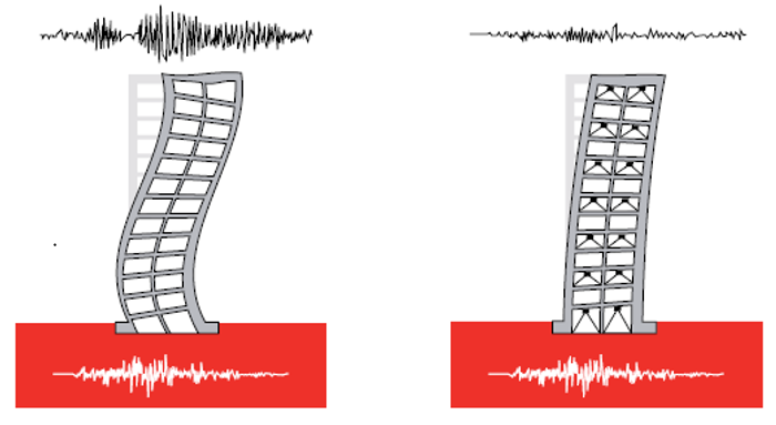
In recent decades, the use of seismic protection systems has increased significantly due to their proven effectiveness. Figure 1 shows a comparison of the behavior of a building without the use of energy dissipators and a building with the use of energy dissipators. The use of energy dissipators, unlike seismic isolators, does not limit the energy input to the structure. The input energy produced by an earthquake is dissipated in the structure through kinetic energy, elastic energy, inelastic energy, and damping energy dissipated by the structural elements.
The performance of the structure can improve if a portion of the input energy can be absorbed by the energy dissipators. This will generate a significant increase in damping energy, which leads to a decrease in the stresses on the structural elements, resulting in a decrease in elastic energy, and especially inelastic energy. This is of vital importance, because the less the structure enters the inelastic range, the less structural damage there will be [4].
The ideal earthquake-resistant structure is one that presents displacements of a rigid system and forces of a flexible system. Energy dissipators concentrate the ductility demands in industrially manufactured elements.
The experimental curves for a scale model of a metal frame are incorporated on decoupled concrete walls in a vibrating table (Figure 2Figure 1 and Figure 3). It is concluded that as the scale factor increases, a system with the level of forces of a flexible system and the level of displacements of a rigid system is achieved [5].
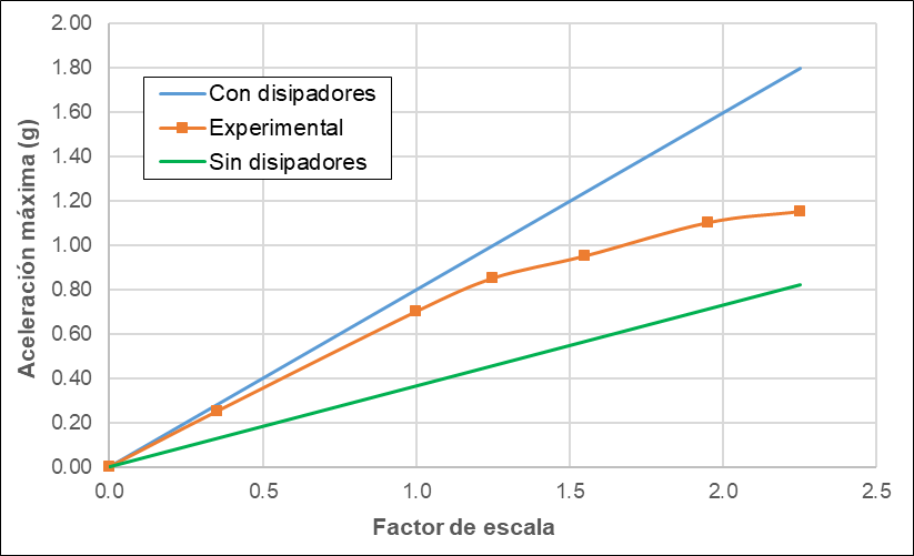
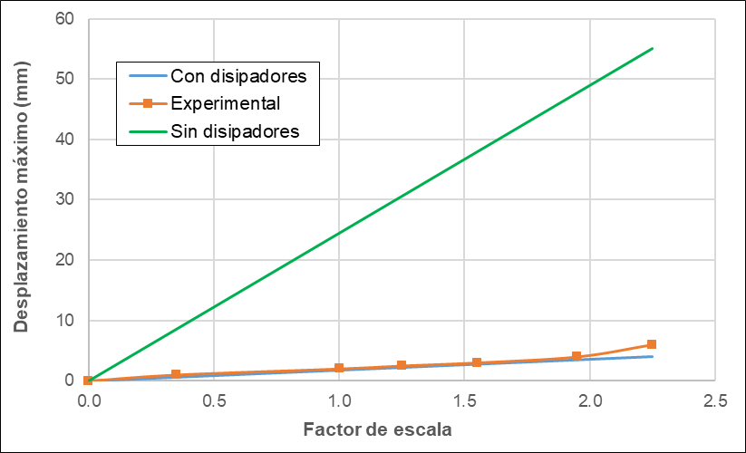
A rigid-flexible-ductile system presents intermediate responses between a flexible system and a rigid system. The maximum use of this concept in a structure lies in optimizing the use of conventional dissipators and walls to adequately control the drifts and at the same time the shear forces do not increase considerably in a flexible system.
The SLB device is based on the localized increase of the building's ductility, allowing a significant reduction in the forces induced by a high-intensity earthquake.
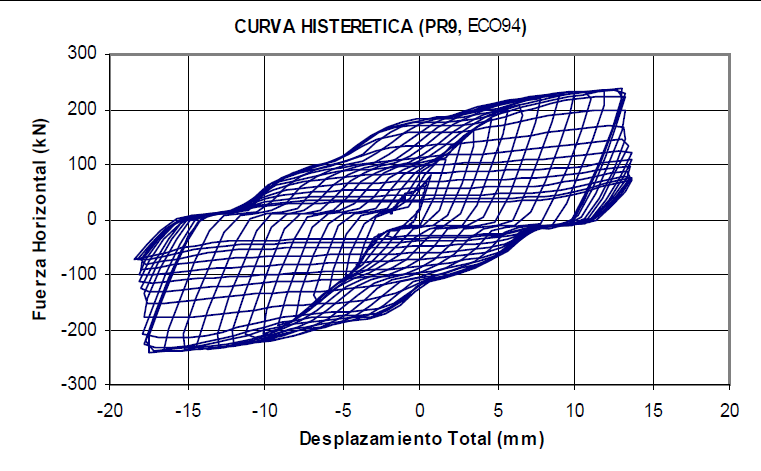
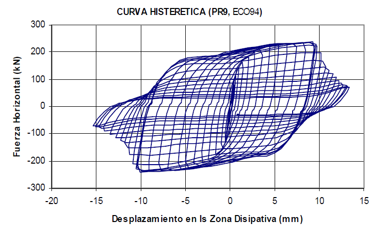
The mounting tolerance of bolted connections influences the dissipators hysteretic curve. Figure 4 and Figure 5 shows two hysteretic curves for the SL30_2 devices subjected to cyclic loads with constant amplitude. If a mounting tolerance of ±1 mm is considered, the metal connections will slip, making response prediction difficult, but the axial force to which they will be subjected will be minimal. Conversely, if the bolted connections are adjusted without considering an mounting tolerance, they will not slip. A hysteretic curve will be obtained that is simpler to model and predict its response, but the device will be subjected to a greater axial force than in the previous case [6]. In conclusion, there is a conflict between achieving ideal behavior in a device, ensuring a stable hysteretic curve, simple modeling to predict its response, and ensuring that it is not influenced by the axial load, since including more parameters makes the development of mathematical models difficult.
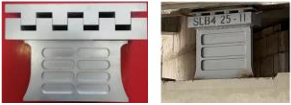
The implementation of energy dissipation systems in a structure allows to modify the capacity design, making dampers the "weak elements" where the damage is concentrated and, therefore, where energy is dissipated. In this paper the metal dampers represented by the so-called Shear Link Bozzo devices are analysed. These devices were subjected to technological developments in the past 20 years, which led to the development of four generations of devices (Figure 6) [7]. The geometry of a second generation SLB devices which is composed of four windows and a square frame (Fig. 4). In addition, the holes on the outside serve to be placed on the Chevron-type wind braces that the portico presents. The design of the steel elements will be carried out in accordance with the AISC 2016 Specification for Structural Steel Buildings [8].
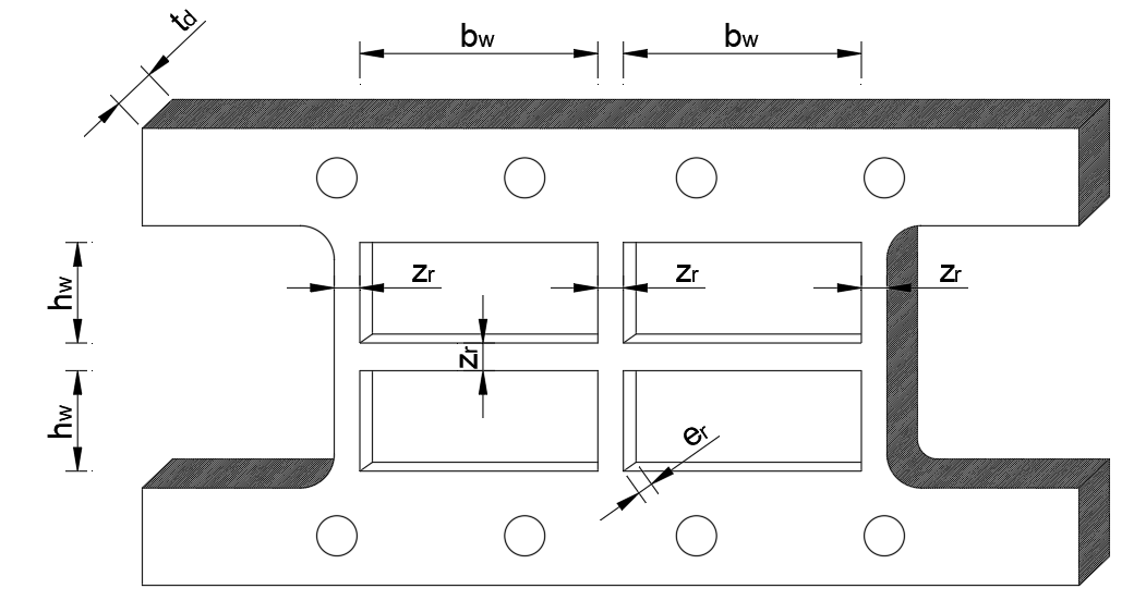
The frame of the SLB device works as a column embedded at its ends, with stiffness kr, while the windows with stiffness kw. The stiffness of the frame and the windows are calculated using the following equations:


Where I is the moment of inertia of the section; hw is the height of a window; E is the modulus of elasticity of steel, G is the shear modulus and Aw represents the shear area of the windows.
An idealized bilinear model simulates the force-displacement behaviour of the SLB dissipator, with a stiffness k1 for the elastic range and k2 for the plastic range. In the elastic range, the windows and the frame work. In the plastic range, only the frame works, since the windows have degraded (Figure 8).


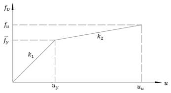
The value α represents the coefficient that relates the plastic stiffness to the elastic stiffness. The window force fw and the frame force fy are related by their stiffnesses, and the yield force ![]() is equal to the sum of the window force plus the frame force.
is equal to the sum of the window force plus the frame force.


3. Methodology
3.1. Diagnosis of Structure State
A diagnosis consists of analysing the current state of a structure, after inspection, data collection and study of the same. In general, it includes the evaluation of the residual capacity, as well as the needs for action and its urgency. In case of damage, the nature, scope, and most probable cause of the same must be determined [9].
3.2. Diagnosis of Structure State
Structural modelling is the process in which the structure is represented in order to analyse its behaviour. Modelling consists of:
- Definition of materials
- Definition of structural elements.
- Definition of load patterns.
- Definition of seismic weight.
- Modelling of the structure.
- Assignment of loads.
- Embedding of supports in the base.
- Assignment of diaphragms.
- Assignment of rigid arms.
- Discretization of shear walls.
3.3. Seismic Analysis Without Dissipators
It consists of determining the response of the structure through the analysis methods established in Standard E.030 [10]. Static analysis represents seismic loads through a set of forces acting on the centre of mass of each level of the building. Spectral modal dynamic analysis allows determining lateral displacements, shear forces per level, stiffness, periods, and masses; the values of which will be verified with the permissible values according to Standard E.030.
3.4. Determination of the Objective Drift
Performance levels describe a damage limit state. They represent a limiting or tolerable condition, established based on the potential structural and non-structural damage to the building, the threat to the safety of building occupants induced by this damage, and the building's functionality after the earthquake [11]. The limiting drift was selected based on the consideration of associating the structure with an operational performance level, where the limiting drift is 0.005.
3.5. Seismic Analysis with Dissipators
It consists of determining the response of the structure with the addition of energy dissipators. The design to be carried out will be iterative; for this procedure it is only necessary to carry out a modal spectral dynamic analysis, in order to save the program's computing time. An adequate number of dissipators is proposed for each frame, these being modelled as NLINK type elements, since their use is more efficient and the structure is ready for a subsequent time history analysis.
3.6. Design of Decoupled Walls
The design of decoupled walls is similar to the design of traditional shear walls, and will be carried out based on the provisions of Standard E.060. Decoupled walls must be designed for the simultaneous action of shear forces and bending moments, but not axial forces due to their particular condition.
4. Case Study
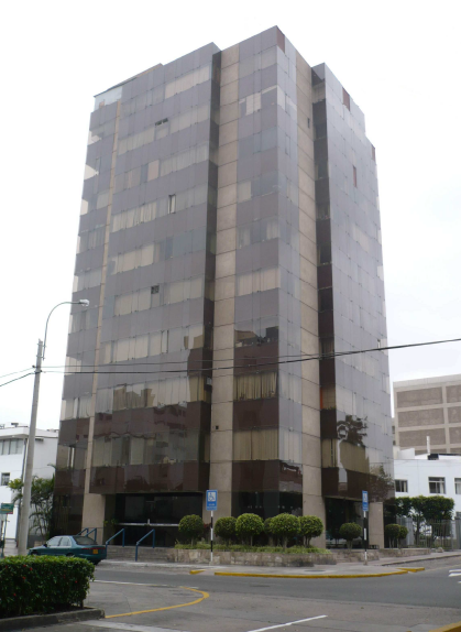
The building to be evaluated is the Anglo-American Clinic, whose project was drawn up in 1983, a 10-story building with a basement, intended for hospital use (Figure 14).
4.1. Diagnosis of Structure State
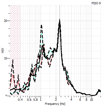
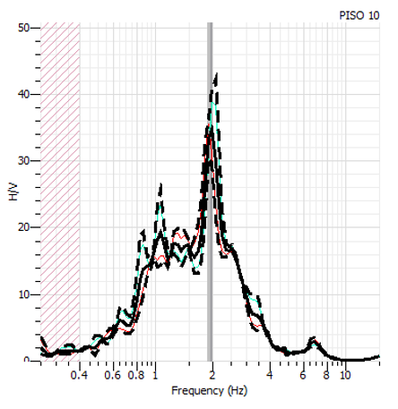
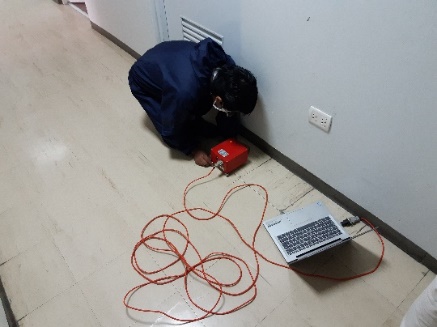
A test of environmental vibrations was carried out where a total of six points were taken in the upper levels using a Sara Geobox 24 Bit Triaxial digital seismograph (Figure 11) to estimate the natural periods in each analysis direction. The Fourier spectra were calculated with the GEOPSY software, this software applies the fast Fourier transform to a signal in the time domain to convert it to the frequency domain. The amplitudes of each frequency are related to the amount of energy that this frequency contributes to the signal, so the peaks in the spectra are associated with the natural frequencies of the system.
The average H/V spectral ratio graphs were obtained – frequency obtained at levels 9 and 10 where two peaks can be observed: the peak of greatest amplitude, whose frequency is approximately 2.50 Hz, and a second peak whose frequency is approximately 1.15 Hz. (Figure 9 and Figure 10).
Using the predominant periods of the structure obtained by the vibration test, a comparative table was made with the periods obtained in the structural model carried out in ETABS (Table 1). The modelled structure shows periods greater than those obtained in the field. Conservatively, it was decided not to adjust the period of the modelled structure to the period obtained in the field. This will provide an additional safety margin when controlling the dynamic response of the structure with dissipators from the maximum values obtained from the analysis.
Table 1. Comparison of periods obtained by environmental vibration testing and ETABS model.
|
Description |
TX (s) |
TY (s) |
TR (s) |
|
Environmental vibration test |
0.860 |
0.860 |
0.460 |
|
ETABS model |
0.996 |
0.926 |
0.673 |
4.2. Seismic Analysis without Dissipators
Table 2 shows the inelastic drifts obtained in both analysis directions, with 0.00815 being the value of the maximum drift in the X direction and 0.00928 in the Y direction. In addition, the difference between the values of the drift in the Y direction can be seen, where the ratio between the maximum drift and the average drift of the ends of the structure in the analysis direction is greater than 1.30 at all levels, so it can be concluded that there is torsional irregularity.
Using the predominant periods of the structure obtained by the vibration test, a comparative table was made with the periods obtained in the structural model carried out in ETABS (Table 1). The modelled structure shows periods greater than those obtained in the field. Conservatively, it was decided not to adjust the period of the modelled structure to the period obtained in the field. This will provide an additional safety margin when controlling the dynamic response of the structure with dissipators from the maximum values obtained from the analysis.
4.3. Seismic Analysis with Dissipators
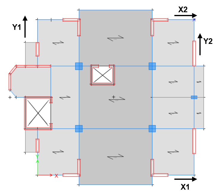
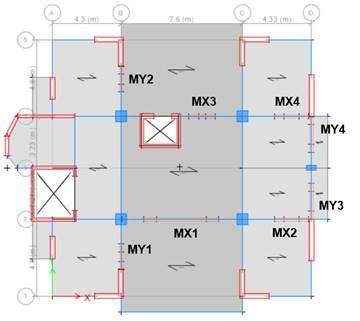
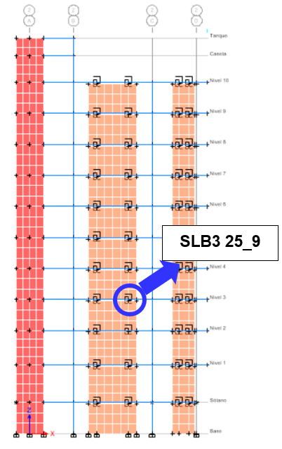
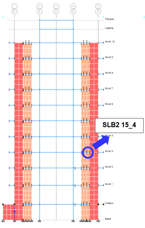
The energy dissipation system will consist of 20 cm decoupled walls in both analysis directions (Figure 13). Inelastic drifts are shown in both analysis directions, whose values are less than the established limit of 0.0050 (Table 3). In addition, the drifts at the ends of the building are very close to each other, so it can be concluded that the structure will have a uniform displacement in both analysis directions and the torsional irregularity that was initially present was corrected.
For the design of the dissipators, the SLB3 25_5 series was assigned for both analysis directions and 3 iterations were performed on average to obtain the most suitable dissipator at each level where the demand-capacity ratio is less than 1.50. A non-linear time-history verification was subsequently performed by selecting a total of 7 sets of matched seismic records, in order to achieve more accurate results, averaging the response.
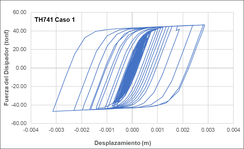
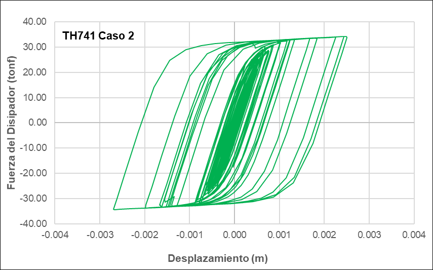
Figure 17 and Figure 18 shows representative hysteresis curves of the dampers for each selected load case. The SLB3 25_8 series damper in the MX1 decoupled wall whose maximum force is 46.81 ton and its maximum displacement is 0.31 cm. In the Y direction, the SLB3 25_5 series damper was assigned whose maximum force is 34.46 ton and its maximum displacement is 0.27 cm.
Table 2. Drifts obtained in structural analysis without dissipators.
|
Level |
∆X1 |
∆X2 |
∆Y1 |
∆Y2 |
|
Level 10 |
0.00637 |
0.00539 |
0.00313 |
0.00644 |
|
Level 9 |
0.00692 |
0.00577 |
0.00351 |
0.00711 |
|
Level 8 |
0.00744 |
0.00610 |
0.00385 |
0.00783 |
|
Level 7 |
0.00785 |
0.00635 |
0.00412 |
0.00850 |
|
Level 6 |
0.00810 |
0.00646 |
0.00428 |
0.00901 |
|
Level 5 |
0.00815 |
0.00641 |
0.00433 |
0.00928 |
|
Level 4 |
0.00793 |
0.00614 |
0.00422 |
0.00923 |
|
Level 3 |
0.00726 |
0.00552 |
0.00389 |
0.00863 |
|
Level 2 |
0.00620 |
0.00463 |
0.00336 |
0.00738 |
|
Level 1 |
0.00381 |
0.00283 |
0.00209 |
0.00429 |
|
Max: |
0.00815 |
0.00646 |
0.00433 |
0.00928 |
Table 3. Drifts obtained in structural analysis with dissipators.
|
Level |
∆X1 |
∆X2 |
∆Y1 |
∆Y2 |
|
Level 10 |
0.00316 |
0.00339 |
0.00375 |
0.00344 |
|
Level 9 |
0.00356 |
0.00374 |
0.00421 |
0.00378 |
|
Level 8 |
0.00400 |
0.00411 |
0.00461 |
0.00417 |
|
Level 7 |
0.00439 |
0.00444 |
0.00487 |
0.00450 |
|
Level 6 |
0.00469 |
0.00468 |
0.00498 |
0.00474 |
|
Level 5 |
0.00486 |
0.00479 |
0.00495 |
0.00486 |
|
Level 4 |
0.00483 |
0.00469 |
0.00471 |
0.00486 |
|
Level 3 |
0.00454 |
0.00431 |
0.00425 |
0.00467 |
|
Level 2 |
0.00424 |
0.00387 |
0.00364 |
0.00429 |
|
Level 1 |
0.00297 |
0.00259 |
0.00237 |
0.00272 |
|
Max: |
0.00486 |
0.00479 |
0.00498 |
0.00486 |
The time-history verification was then carried out, where the drifts for each seismic recording case must be less than 0.00625 to conclude that the seismic analysis is adequate (Figure 19 and Figure 20).
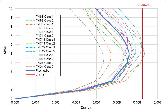
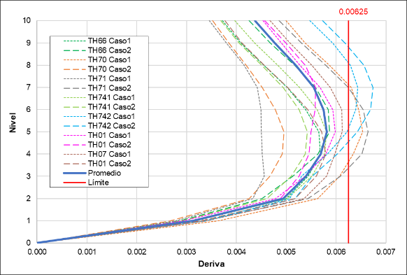
Table 4. Seismic records considered for analysis.
|
Code |
Date |
Station |
Duration |
Component |
amax |
|
|
Name |
Code |
(s) |
cm/s2 |
|||
|
TH66 |
October 17, 1966 |
Reserve Park (Lima) |
PRQ |
65.64 |
EW |
180.56 |
|
NS |
268.24 |
|||||
|
TH70 |
May 31, 1970 |
Reserve Park (Lima) |
PRQ |
45.16 |
EW |
105.05 |
|
NS |
97.81 |
|||||
|
TH71 |
November 29, 1971 |
Reserve Park (Lima) |
PRQ |
40.12 |
EW |
53.66 |
|
NS |
86.21 |
|||||
|
TH741 |
October 3, 1974 |
Reserve Park (Lima) |
PRQ |
97.96 |
EW |
194.21 |
|
NS |
180.09 |
|||||
|
TH742 |
January 5, 1974 |
Zarate (Lima) |
ZAR |
32.80 |
EW |
138.94 |
|
NS |
156.30 |
|||||
|
TH01 |
June 23, 2001 |
Cesar Vizcarra Vargas (Moquegua) |
MOQ001 |
198.91 |
EW |
295.15 |
|
NS |
219.99 |
|||||
|
TH07 |
August 15, 2007 |
UNICA |
ICA002 |
218.06 |
EW |
272.82 |
|
NS |
333.66 |
|||||
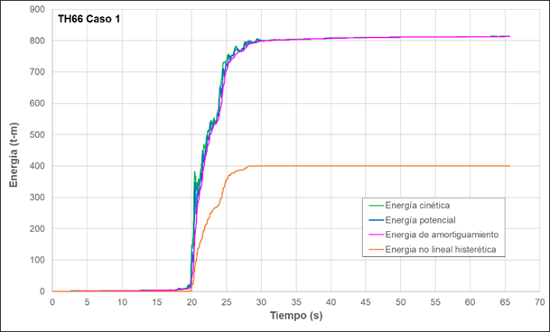
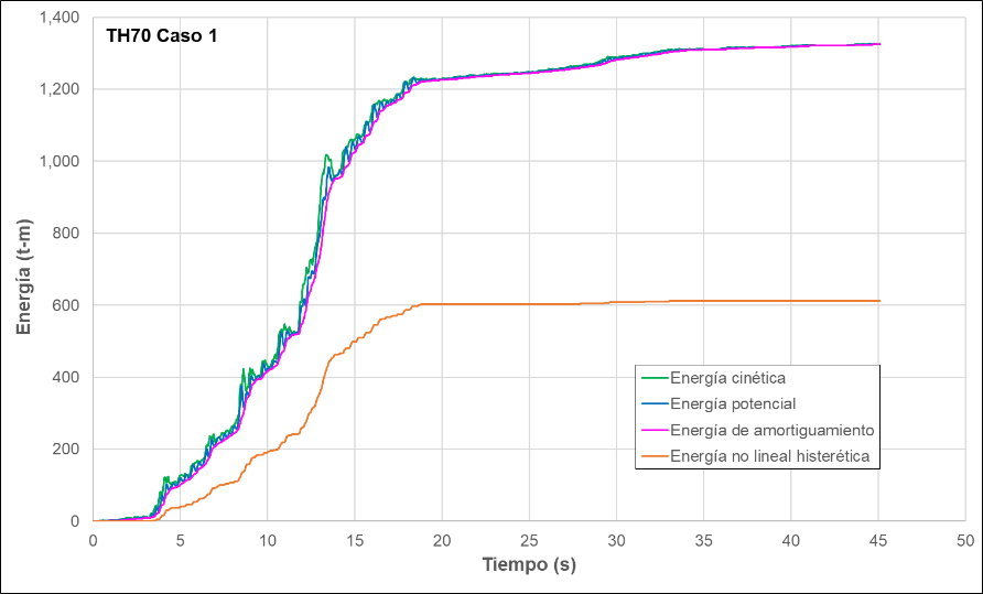
Figure 21 and Figure 22 represents the energy dissipated in the structure for the selected load cases. Hysteretic nonlinear energy is dissipated by the SLB dissipators and represents an average of 46% of the input energy.
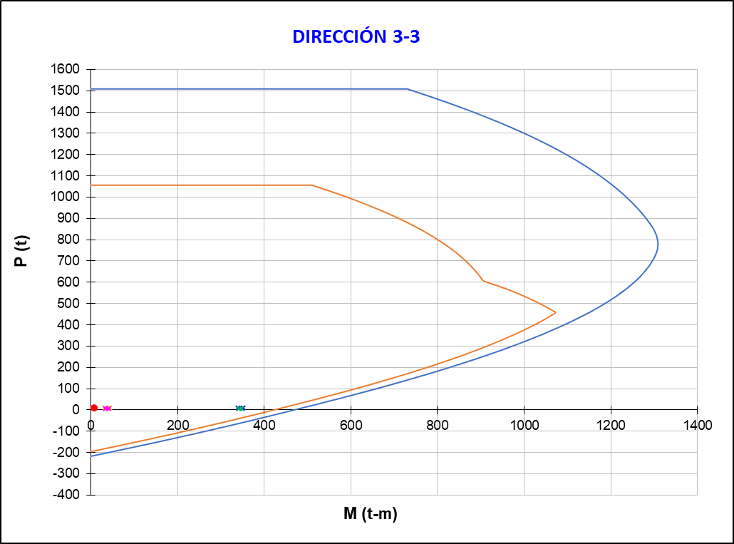
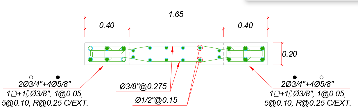
4.4 Design of Decoupled Walls
The decoupled walls with the greatest shear force on each axis were selected for the application design. It can be seen that the walls only support axial forces generated by their own weight, so the design will be performed using bending and shear.
As an example, the design of wall MX1 will be carried out in detail. The design begins by filtering the loads acting on the wall.
The shear design will be performed by capacity, in accordance with Article 21.9.5 of Standard E.060 [12]. An additional amplification must be considered due to the ratio of the nominal moment to the ultimate moment due to the load combination under analysis. It should be noted that the capacity cut design may be limited to a wall height measured from the base equivalent to the length of the wall or the height of the first two floors, whichever is greater.
5. Conclusions
The ambient vibration test performed on the Anglo-American Clinic Medical Center Tower provided the actual periods of the structure, which served as a reference for verifying the structural model created in ETABS. The periods were adjusted in the computer program by modifying the modulus of elasticity until they reached similar values. This ensured that the structural model's behavior was as close as possible to the structure's actual behavior, and that the design requirements for the dampers were no greater than necessary.
The maximum drift in the X direction was reduced from 0.00815 to 0.00486 with the addition of the SLB dissipators, representing a 40% reduction. In the Y direction, the maximum drift was reduced from 0.00928 to 0.00498, representing a 46% reduction. Both drifts are within the limit that was established to ensure the functionality of the structure after a seismic event.
Analysis using seismic records verified that the average of the drifts obtained for the seven selected seismic record sets is less than the established limit value. In the X direction, an average maximum drift of 0.0054 was obtained, and in the Y direction, an average maximum drift of 0.0058 was obtained, both values less than the established limit value of 0.00625.
The addition of SLB dissipators to the structure reduced the percentage of energy dissipated by the structure to an average of 46% for the selected load cases.
The proper location of the dissipators in the plan is important to correct structural irregularities. In the Y direction there was torsional irregularity, the relationship between the maximum drift and the average drift of the ends of the structure was 1.38. By adding dissipators, this relationship was reduced to 1.07, giving the structure uniform displacements.
7. References
[1] Complementary technical standards for seismic design (2020). Buildings with seismic energy dissipators, Appendix B, Government of Mexico City.
[2] National Institute of Civil Defense INDECI (2009). Statistical Compendium on Disaster Prevention and Response 2007, Lima.
[3] Pantoja M., Bozzo G., Alva R., Pérez L., Davalos E. and Bozzo L. (2024). Seismic Performance Evaluation of an irregular and Slender Skyscraper utilising Stiff Dampers, 18th World Conference on Earthquake Engineering, Milan.
[4] Constantinou, M., Soong, T. y Dargush, G., (1998). Passive Energy Dissipation System for Structural Design and Retrofit, Multidisciplinary Center for Earthquake Engineering Research - MCEER, New York.
[5] Bozzo L. and Gaxiola G. (2015). The rigid-flexible-ductile concept and SLB connections, XX National Congress of Earthquake Engineering, Guerrero.
[6] Hurtado, F. (2006), Proposal for a generic SL dissipator for buildings and its Earthquake-Resistant Design, Doctoral thesis, Polytechnic University of Catalonia, Barcelona.
[7] Del Vecchio F., Serino G., Formisano A. and Bozzo L. (2024). Design Optimization of High-Rise Buildings Equipped with Outrigger Systems and SLB Devices, 18th World Conference on Earthquake Engineering, Milan.
[8] AISC (2016). Specification for Structural Steel Buildings. Illinois.
[9] Río Bueno A. (2008). Pathology, repair and reinforcement of reinforced concrete building structures, Polytechnic University of Madrid.
[10] SENCICO (2018). National Building Regulations. Technical Standard E.030 Earthquake-resistant design, Lima.
[11] ASCE/SEI 41 (2017). Seismic evaluation and retrofit of existing buildings. Published by American Society of Civil Engineers.
[12] SENCICO (2009). National Building Regulations. Technical Standard E.060 Reinforced Concrete, Lima.