International Journal of Civil Infrastructure (IJCI)
ISSN: 2563-8084

Volume 8 - Year 2025- Pages 227-234
DOI: 10.11159/ijci.2025.023
Estimation of Friction Coefficient of Movable Bearings based on Thermal Displacement
Kota Dobashi1, Yuichi Ito1, Kouichi Takeya1, Eiichi Sasaki1
1Institute of Science Tokyo, Civil Engineering
W6-7, 2-12-1 Ookayama, Meguro ward, Tokyo prefecture, Japan, 152-8550
dobashi.k.68e1@m.isct.ac.jp; ito-y@fa2.so-net.ne.jp; takeya.k.aa@m.titech.ac.jp; sasaki.e.ab@m.titech.ac.jp
Abstract - Movable bearings are expected to respond to bridge expansion and contraction due to temperature changes and train loads. However, due to the friction within a bearing, actual bearing movement tends to be smaller than theoretical prediction. This discrepancy between actual situation and theoretical evaluation can suggest that girder expansion or contraction is constrained, thereby causing stresses and frictional reaction forces at the bearing seat. Although bearing friction is expected to increase with age, there is no standardized method for evaluating the friction coefficient, making it unclear when preventive maintenance actions should be implemented. This study aims to estimate the friction coefficient of bearings in actual bridges using finite element method (FEM) analysis and field measurements. The measurements have revealed a characteristic behavior whereby the bearings initially stick and then slip. This bearing behavior was then reproduced using numerical simulation, demonstrating the feasibility of estimating the friction coefficient of movable bearings under in-service conditions.
Keywords: Bearing Friction, Friction Coefficient, Bearing Behavior, Temperature Change.
© Copyright 2025 Authors - This is an Open Access article published under the Creative Commons Attribution License terms. Unrestricted use, distribution, and reproduction in any medium are permitted, provided the original work is properly cited.
Date Received: 2025-05-26
Date Revised: 2025-09-26
Date Accepted: 2025-10-20
Date Published: 2025-12-22
1. Introduction
Movable bearings are expected to respond to bridge expansion and contraction due to temperature change and train loads. However, Kawada et al. [1] state that bearing is prone to damage, and Nishida et al. [2] and Shono et al. [3] show that the number of damaged shoe seat mortar is also not small, and such damage is most common in the line bearings according to Shono et al. [3]. Nishida et al. [2] and Nara [4] show that the bearing’s adherence worsens during the time it is in service. In fact, from Sugawara et al. [5], there is a case of adhered line bearings. In this case, the girder expansion and contraction became fixed by these adhered bearings and consequently the girder applied a force onto the bearings, causing them to move. Practically, Structures Design Office [6] states that damage to the shoe seats may occur due to sticking of the movable bearing.
According to Structures Design Office [6], about measures for bearing sticking, although qualitative assessments such as the degree of corrosion and wear, quantitative evaluation of such sticking has not been conducted. Therefore, to take specific countermeasures at the appropriate time is difficult. Niwa et al. [7] obtained friction coefficient of a movable bearing under in-service condition by determining the force in the direction of the bridge axis acting the bearing from the measured stress distribution in the girder and dividing it by the dead load acting on the bearing. Reading Niwa et al. [7], it is considered that this method requires many measurement points because the stress distribution in the girder is not uniform.
This research aims to evaluate the bearing adhesion degree to contribute to decision-making, such as when and what bearing countermeasure is suitable, in the maintenance phase. First, the movement of bearings under temperature change, which is considered to be affected by the bearing friction coefficient, was investigated using actual measurements and analysis. Based on these results, the possibility of estimating friction coefficients for in-service bridges has been demonstrated. To establish a more versatile method, this research has further explored a method to derive the friction coefficient by focusing on the movement of the bearing, which requires only one measurement point.
2. Field Measurements on Actual Bearing Behavior
2. 1. Target Bridge
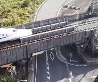
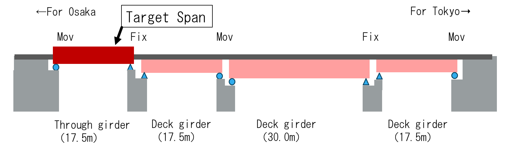
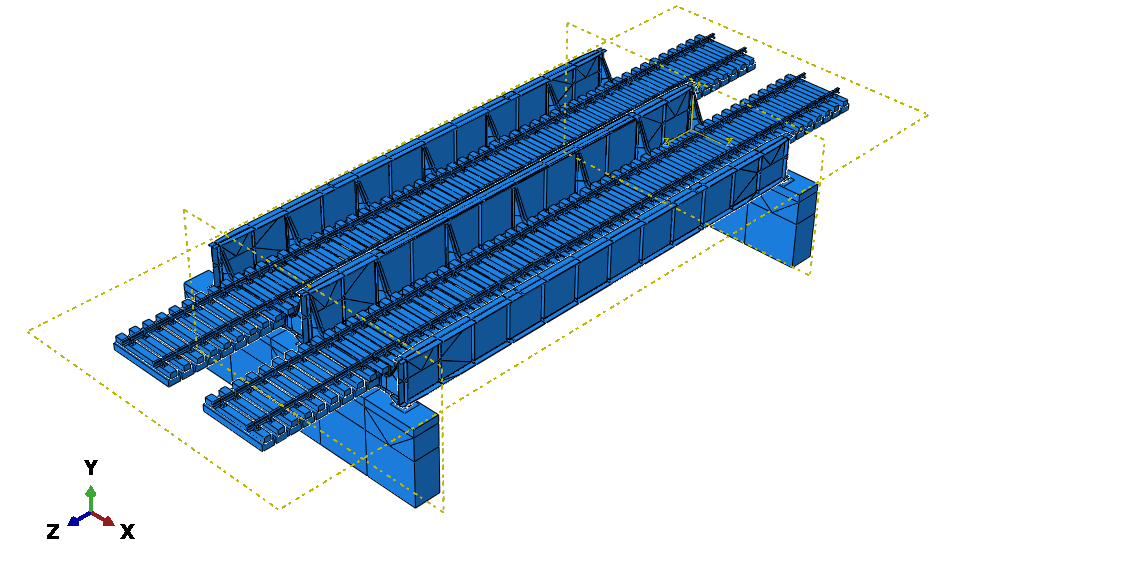
To investigate bearing movement caused by temperature change or the passage of a train, field measurements were conducted on a target bridge along the Tokaido Shinkansen line. The target span of the bridge is shown in Figure 1 and a general view of the bridge is shown in Figure 2.
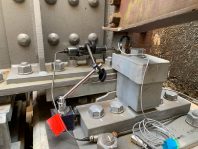
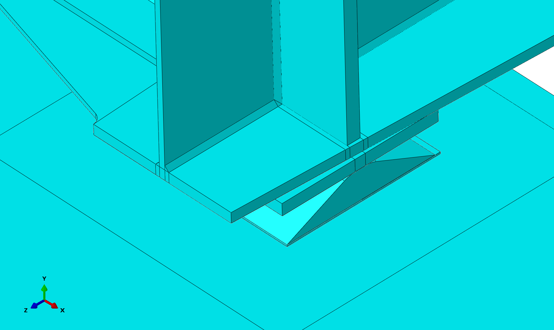
The target bridge consists an open-floor, through which a separate plate girder bridge with three main girders and two tracks passes. The span length of the target section is 17.5 m. Continuous welded rails are used in this section, and there are no rail joints within the target span. Since its opening in 1964, the target bridge has undergone several reinforcements and soundproofing upgrades. The bridge employs line bearings, as shown in Figure 3, which were recently replaced as part of maintenance activities. The bridge experiences frequent train passage during daytime hours. However, no commercial trains operate between 0:00 and 6:00, and only maintenance vehicles pass.
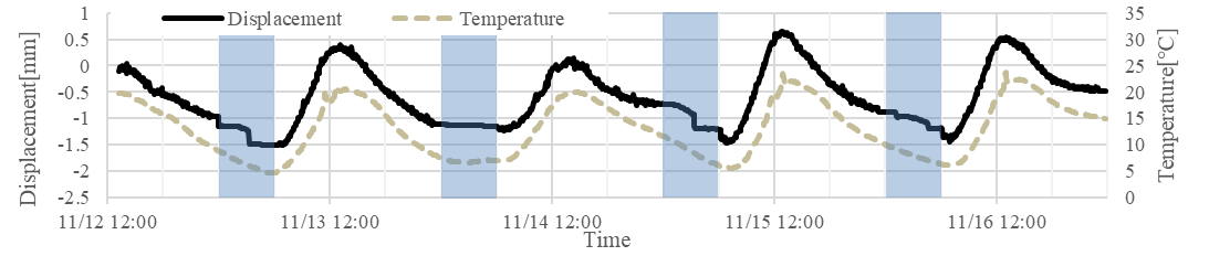
2. 2. Temperature-Bearing Displacement Relationship
The temperature-displacement relationship of the target bridge was measured over a four-day period as shown in Figure 4. The member temperature was measured near the movable bearing of the central girder, and the bearing displacement was measured at the movable bearing on the northern side of the three main girders. The displacement was considered positive in the direction of girder expansion. The location of the displacement meter is also shown in Figure 3.
The displacement transducer used was either a PI-type (Tokyo Measuring Instruments Laboratory Co. Ltd. PI-5-50) or a contact-type (Tokyo Measuring Instruments Laboratory Co. Ltd. CDP-50), where a coin-type thermos-hygrometer was used as the thermometer.
In Figure 4, the shaded sections indicate late-night hours between 0:00 and 6:00. Figure 4 shows that although bearing displacement generally changes in response to temperature changes between 6:00 and 24:00 on each day, it remains constant, decreases gradually, or changes abruptly during the late-night hours between 0:00 and 6:00. We focus on each of these two curves.
2. 3. Bearing Movement During Daytime
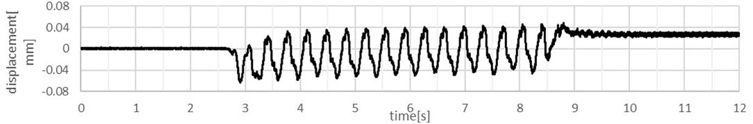
Firstly, bearing movements during daytime hours between 6:00 and 24:00 were considered. During this period, many commercial trains pass. The waveform shown in Figure 5 represents the bearing displacement by train passage.
Niwa et al. [7] pointed out that the change in the horizontal displacement of the bearings before and after the train passage indicates that the friction-constrained thermal expansion and contraction of the bearings is released by the train passage. During the daytime, the trains passing impact cause bearing displacement, and the bearing is considered to follow the temperature change of the girder with small increments of movement as in Niwa et al. [7].
2. 4. Bearing Movement During Late-Night Hours
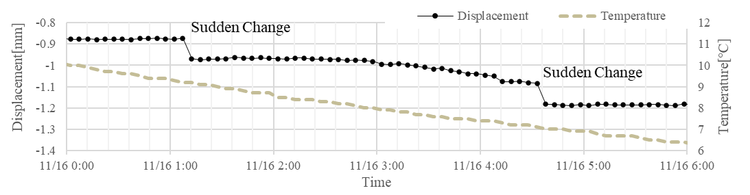
Next bearing movements during late-night hours between 0:00 and 6:00 were considered. During this period, the bearing displacements either fluctuated abruptly or remained constant initially and then gradually decreased. These characteristic movements are shown in Figure 6, where the measurements were recorded on 16 November.
The sudden change observed in bearing displacements in Figure 6 is considered to have occurred due to the passing of a maintenance vehicle, which abruptly releases previously restrained displacements.
For the latter movement, although the test was conducted for different type of bearing from the target bridge, Nishida et al. [2] conducted loading tests on bearings and showed that the behavior of static and dynamic friction appears when stainless steel slides against each other. Therefore, the bearings did not move due to the absence of frequent impacts from commercial trains passing during late-night hours. However, under decreasing temperatures and when the thermal tensile axial force of the girder reached the maximum static frictional force of the bearing, bearing started to slide, causing the displacement to gradually decrease. Figure 7 shows an example of such a case, which occurred during the night of 16 November, the same day as the experiment conducted for Figure 6.
The thermal tensile axial force of the girder acting on the bearings were considered to be proportional to temperature changes. When the bearing started to slide, it was considered to be balanced by the maximum static friction force. In other words, the temperature range between when the bearing begins to adhere and when it starts to slide should be proportional to the friction coefficient.
Thus, it was found that the bearings generally followed the temperature during the daytime. However, the effect of bearing friction became apparent during the nighttime. FEM analysis of the target bridge was conducted to reproduce the bearing movements shown in Figure 7 and determine the coefficient of proportionality between the bearing friction coefficient and temperature range.

3. Consideration Bearing Behavior using FEM Analysis
FEM analysis was conducted to reproduce the bearings movements shown in Figure 7 and to investigate the relationship between the friction coefficient and temperature change.
3. 1. Model Settings
The overall bridge model used for analysis is shown in Figure 8. Abaqus 2017 software was used for analysis. The target bridge features line bearings, constructed in the model as shown in Figure 9. The movable bearing side includes a contact element, while the fixed bearing side features a fixed contact element between the bottom shoe and the sole plate. Bearing friction was modeled using the Lagrange multiplier method between the bottom shoe and the sole plate of the movable bearings.
Boundary conditions were set at the underside and backside of the abutments, the underside of some ballasts, and at the rail ends. The boundary conditions restricted displacement and rotation in all directions for the underside and backside of the abutments, displacement in all directions for the underside of the ballasts, and displacement in the rail axial direction for the rail ends. The piers were reproduced; however, their dimensions did not match the original specifications. The continuous welded rail, lower lateral bracing, and brake truss were also reproduced.
The material parameters used for analysis are shown in Table 1. The stiffness of both the members connecting the lower lateral bracing to the longitudinal girders and the brake truss were sufficiently increased to suppress deformation and their temperature is constant. The rail linear expansion coefficient was set to zero.

3. 2. Loading Condition
The effect of the movable bearing friction on the constrained thermal expansion and contraction of the girder was then examined. In this analysis, the bridge was loaded with its own weight and a friction coefficient was applied on the movable bearings. Next, the temperature of the bridge members was uniformly increased. A total of three cases was initially analyzed, where the friction coefficients of the movable bearings were set to 0.2, 0.5, and 0.8.
The analysis reproduced bearing movement during the late-night period as there are no commercial trains in this period and train loads can be excluded.
3. 3. Temperature and Displacement Relationship
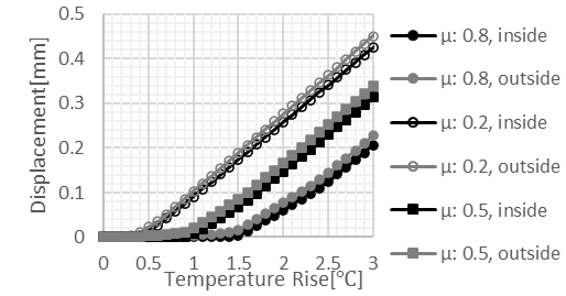
Figure 10 illustrates the relationship between the rise in temperature of bridge members and the relative displacement between the bearing and the sole plate along the bridge axial direction for each analysis. The displacements were extracted from two points near the tangent line between the sole plate and the lower shoe in the side girder bearing; namely the inner and outer points for the bridge, perpendicular to the bridge axis. Initially, no displacement was observed, however, after the temperature reached a certain threshold, displacement increased in an approximately linear manner. The thermal load of the girder due to the restrained expansion and contraction of the girder is assumed to have exceeded the maximum static friction force of the movable bearing, causing the bearings to move.
Figure 10 shows a similar behavior to Figure 7 as the bearing displacement initially remains constant before increasing or decreasing linearly from a certain temperature. Therefore, we can estimate the friction coefficient from the measured temperature , where the bearings begin to slide, by comparing with the analysis result.
3. 4. Difference due to Friction Coefficient
The relationship between the temperature at which the bearings begin to slide (denoted as ∆T) and the friction coefficient (denoted as μ) is shown in Figure 11. Linear approximation of the friction coefficient μ and temperature ∆T results in ∆T=1.8602μ (referred to as Eq. (1)), with an R-squared value of 0.9994.
Therefore, there is a strong correlation between the friction coefficient μ and the temperature ∆T when the bearings begin to slide. This suggests that the friction coefficient of the bearings can potentially be assessed.
Considering the formula based on the bending theory of beams, an equation for the relationship between the temperature ∆T and the friction coefficient μ was derived in a simplified manner.
In this equation, the cross-sectional area of the girder is represented as A, the modulus of elasticity is denoted as E, the sectional secondary moment is represented by I and the coefficient of linear expansion is expressed as α. The dead weight acting on the bearing is referred to as w and the distance between the sole plate underside point where the bearing friction force is applied and the neutral axis of the girder is denoted by l. The cross-sectional area of the girder is assumed to be equal to the minimum cross-sectional area. The dead weight acting on the bearings is calculated as 7.74 × 10⁴[N], which is obtained by distributing the weight of the analytical model with considering vertical stresses in the bearings. The vertical stresses do not completely include the weight of the members connecting the lower lateral bracing to the longitudinal girders and brake trusses. Nonetheless, this effect is expected to be negligible.
The main girder is subjected to a bending moment of lwμ by the maximum static friction force just before the bearings begin to slide. Since the bearings are sticking, the displacement is zero at the underside of the sole plate, and the girder strain on the underside of the sole plate remains equal to the thermal expansion strain of α∆T. Applying the formula for the strain of a simply supported beam subjected to bending moment, we obtain Eq. (2) as below.
Figure 11 also shows the relationship between the friction coefficient μ and the temperature ∆T using Eq. (1) - (2). Eq. (2) calculated the temperature ∆T to be 15.0% higher than the analytical Eq. (1).
3. 5. Difference due to Continuous Welded Rail
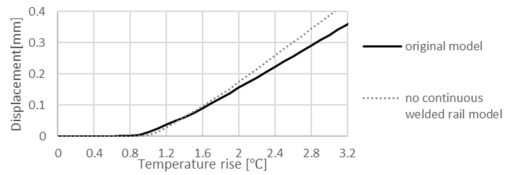
The effect of continuous welded rails has also been considered in this study. According to Railway Technical Research Institute [8], the continuous welded rail constrains the girder expansion and contraction, which affects the movement of the bearings. Figure 12 shows the movements at the bearing center points. One is based on a friction coefficient of 0.5 (denoted as ‘original model’), and the other is observed when the stiffness of the continuous welded rail, brake truss, and lower lateral bracing decreases to 200 MPa for the same model (denoted as ‘no continuous welded rail model’).
In Figure 12, the temperature at which bearing started to slide slightly increased for the model without continuous welded rails. Regarding the slope of the bearing displacements during bearing sliding, the original model showed a smaller slope compared to the model without continuous welded rails, which is considered to be due to the restraint applied to the bridge girder from the continuous welded rail.
4. Comparison between Measurements and Analysis
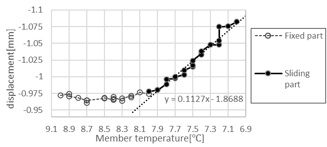
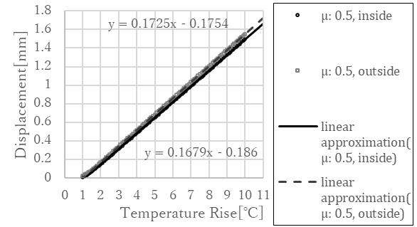
In this section, we compare the measurement and analysis results for accuracy verification. Figure 13 shows the temperature-displacement relationship in bearing sliding part in Figure 7 with a linear approximation line. Figure 14 shows Figure 10 with linear approximation lines added to the displacements of the inner and outer sides in the bearing. Figure 14 contains only the results when the friction coefficient is 0.5 and for bearing sliding section, where the temperature rise exceeded 1 degree of Celsius. The graph display range is expanded.
In this research, we can compare the measurement and analysis by temperature change in bearing sticking section or slope of displacement and temperature change in bearing sliding section. In actual bridge, bearing friction coefficient is not clear and comparison in the sticking section is difficult. Therefore, in this research, we compare measurement and analysis by the slope in the sliding section. Comparison using slope between displacement and temperature change is also conducted in Niwa et al. [7].
The measured slope of the temperature-displacement relationship in Figure 13 linear approximation line is 0.1127[mm/℃]. In contrast, the analytical slope of the temperature-displacement relationship in Figure 14 linear approximation line is 0.1725[mm/℃] on the bridge outer side of the bearing and 0.1679[mm/℃] on the bridge inner side of the bearing. Using the measured values as a reference, the analytical temperature-displacement slopes have error of approximately 50%. That indicates that the bridge girder thermal load to the bearing has not been correctly evaluated in analysis. Therefore, it is considered inappropriate to use the relationship between the temperature change in bearing sticking section and the bearing friction coefficient obtained or set in this analysis to estimate the bearing friction coefficient in actual bridge.
The reproduction of bridge members which can affect girder expansion or contraction as mentioned in Railway Technical Research Institute [8], the existence of temperature difference as mentioned in Kobayashi et al. [9] and Niwa et al. [7], and displacement of bridge pier as mentioned in Nishimura [10] and Tokunaga et al. [11] are not considered fully and the error investigation is one of the future issues.
The reason of small difference in the analytical slopes of the temperature-displacement relationship between the inner and outer sides of the bearing is considered to be the distance from continuous welded rail, which constrain the bearing displacement.
5. Conclusion
This study shows that it is potentially feasible to estimate the friction coefficient by considering the movement of a bearing under temperature change, which can enhance bridge maintenance efficiency. The findings are summarized as follows:
- Field measurements have shown that under frequent train passage, bearings move in response to temperature change, whereas under less frequent train passage frictional effects prevail and the bearing does not move. Bearing movements resulted in gradual displacement after sticking during infrequent train passages. This suggests that the friction coefficient can be estimated from bearing behavior.
- The analysis conducted in this study shows that during temperature change, the movable bearings remain initially stationary then begin to slide once the absolute temperature change reaches a specific threshold. A strong correlation therefore exists between the absolute temperature change during bearing sticking and the friction coefficient.
This research attempts to estimate the friction coefficient of the bearing and show the possibility of estimation; however, the accuracy remains uncertain. Enhancing the accuracy of friction coefficient estimations remains a challenge to be considered in future studies. The estimation method of friction coefficient is based on the theory that bearing sliding start temperature depends on bearing friction coefficient. Therefore, if bearing shows sticking-sliding movement originating from friction, we can estimate the coefficient, although it may contain a certain degree of error, using this method.
Acknowledgements
We would like to thank Mr. Hirai in Central Japan Railway Company for his assistance with conducting field measurements and analysis in this study.
References
[1] S. Kawada, T. Tsukahara, T. Kubota and Y. Matsuda, "Measures for deterioration of railway bridge bearings in JR EAST," Infrastructure Maintenance Practices, JSCE, vol. 1, no. 1, pp. 445-451, March, 2022.
[2] H. Nishida, M. Kimura, F. Yamada, T. Furuichi and S. Matsui, "Development of replacement bearing in steel railway bridge," Journal of Structural Engineering, JSCE, vol. 65A, pp. 419-431, March, 2019.
[3] I. Shono, Y. Yamada and S. Matsui, "A database for the damage near the bearing support," Proceedings of Annual Conference of the Japan Society of Civil Engineers, vol. 49, Division 1, pp. 342-343, 1994.
[4] I. Nara, "[Support structures of steel railway bridges]," Structural Design Data, no. 4, Japanese National Railways, pp. 132-139, 1965. (in Japanese)
[5] T. Sugawara, H. Onishi and M. Satomi, "Estimation of bearing movement status and quantitative evaluation of restraint status in road bridge behavior measurement," Journal of the Society of Materials Science, Japan, vol. 71, no. 3, pp. 303-309, March, 2022.
View Article
[6] Bureau of Facilities, Structures Design Office, "[Guideline for Repair of Steel Railway Bridge Bearings]," December, 1984, pp. 5-11, 17, 21. (in Japanese)
[7] Y. Niwa, S. Yajima, Y. Takahashi and K. Komon, "Behavior of the bearings with bearing plate of the railway composite girder bridge used for 38 years and evaluation of axial force acting on the bearings," Journal of Structural Engineering, JSCE, vol. 64A, pp. 421-434, March, 2018.
[8] Railway Technical Research Institute, "[Design Standards and Commentary for Railway Structures: Steel and Composite Structures]," Maruzen Co., Ltd., October, 1992, pp. 19, 22-23, 32-34, 40-41, 46-47, 55-56, 91-98, 224-226. (in Japanese)
[9] Y. Kobayashi, C. Miki and A. Tanabe, "Health monitoring utilizing thermal deformation for box girder bridge with orthotropic deck system," Japanese Journal of JSCE A, vol. 62, no. 4, pp. 794-807, October, 2006.
View Article
[10] A. Nishimura, "[Effect of continuous welded rail vertical load on bridge piers]," Structural Design Data, no. 75, Japanese National Railway Structures Design Office, pp. 19-23, 1983. (in Japanese)
[11] N. Tokunaga, M. Yoshikawa, S. Kawakita and Y. Yamamoto, "A study about validity of exchange from bearing with bearing plate into rubber bearing," Japanese Journal of JSCE, no. 581/VI-37, pp. 17-25, December, 1997.
View Article