International Journal of Civil Infrastructure (IJCI)
ISSN: 2563-8084

Volume 7 - Year 2024- Pages 32-42
DOI: 10.11159/ijci.2024.004
Assessing the Seismic Performance of Underground Infrastructures to Near-Field Earthquakes
Marco Civera1, Matteo Dalmasso1, and Bernardino Chiaia1
1Department of Structural, Geotechnical and Building Engineering, Politecnico di Torino
Corso Duca degli Abruzzi 24, 10129 Turin, Italy
marco.civera@polito.it; matteo.dalmasso@polito.it, bernardino.chiaia@polito.it
Abstract - Assessing the seismic response in road and rail tunnels is crucial for ensuring their structural integrity and safety as vital infrastructures. However, these underground spaces receive far less scrutiny compared to their above-ground counterparts such as bridges and viaducts. Moreover, comprehensive case studies with fully dynamic monitoring systems, especially in active seismic zones, are uncommon. The dynamic behaviour of man-made tunnels varies significantly based on factors like design and geological conditions, particularly the surrounding soil or rock characteristics. Tunnels excavated in shallow depths within soft soils are generally considered more susceptible to seismic forces compared to those bored through dense soil or hard rock. However, direct comparisons based on experimental data are limited in the current scientific literature. To this aim, the seismic responses of one underwater rail tunnel and two nearby mountain road tunnels to the same near-field seismic event are examined. Specifically, data from the Mw=4.4 Berkeley Earthquake on the Bay Area Rapid Transit's Transbay Tube and Caldecott tunnel system's Bore 3 and 4 are analysed. This represents a rather unique case for near-fault strong motions, which are the ones expected to be most dangerous for civil structures and infrastructures. Moreover, this set of target infrastructures includes different boundary conditions (soft soil and hard mountain rock), cross-sectional shapes, year of construction, and other characteristics. This enables a detailed investigation of these contributing factors. Finally, Arias Intensity (AI) and significant duration (Ds595) are proposed as potential explanations for the different seismic susceptibility of these different tunnels.
Keywords: Seismic Response, Underground Spaces, Earthquake Engineering, Soft Soil Tunnelling, Rock Tunnelling.
© Copyright 2024 Authors - This is an Open Access article published under the Creative Commons Attribution License terms. Unrestricted use, distribution, and reproduction in any medium are permitted, provided the original work is properly cited.
Date Received: 2023-12-15
Date Revised: 2024-04-29
Date Accepted: 2024-05-01
Date Published: 2024-06-10
1. Introduction
This work’s main intent is to put forth the issue of seismic susceptibility in underground infrastructures. In fact, the seismic robustness and resilience of below-ground structures and infrastructures are much less studied than their over-ground counterparts.
Common engineering experience and decades of documented earthquake aftermaths show that underground structural elements, especially deep ones bored in rock or hard soil, are far less vulnerable to strong motions than superficial ones. Many causes are speculated to contribute to this; for instance, it has been proved that the ground motion at the structure basis can be amplified by the response of the structure itself, reaching an extent such that the induced strains damage the structure, or at least its most vulnerable components [1].
Monitoring tunnels and underground infrastructures is critically important for several safety-related motivations, especially in seismically active regions. Many past events – which will be discussed more in detail in the next Section – indicate how earthquakes can cause severe structural damage to tunnels, especially through mechanisms like liquefaction (more common in shallow, water-saturated soils), ground deformation, and fault relative movements.
In this regard, vibration-based Structural health monitoring (SHM) systems are crucial for assessing the seismic resilience of tunnels, providing real-time data on accelerations, displacements, and dynamic strains.
Even in the absence of strong ground motions, monitoring tunnel vibrations and deformations is essential both during construction and throughout the service life of the tunnel.
In fact, in the first case, the excavation process during tunnel construction is known to potentially trigger microearthquakes; that issue further emphasises the need for continuous monitoring to ensure the stability and safety of the tunnel at the time when it is most at risk. In the second case, permanent monitoring is the only way to continuously control the current condition of the infrastructure, checking material ageing issues before they become excessively hazardous, allowing for early damage detection and enabling proactive safety measures.
The remainder of this paper is organised as follows. Section 2 describes in detail the context and known state-of-the-art for the topic under investigation here. Section 3 presents the case studies used for this comparative analysis. Section 4 reports the first set of results, based on a time-frequency analysis. Similarly, Section 5 provides a second set of results, this time based on Arias Intensity and significant duration. The Conclusions (Section 6) follow.
2. Related works on the seismic structural risk of above and below-ground infrastructures
On the one hand, numerous studies in the literature focus on the seismic behaviour of above-ground infrastructures (i.e., road and rail bridges and viaducts), with references such as [2-4], also with an emphasis on near-fault events [5] and accounting for geotechnical soil-structure interactions [6]. On the other hand, there is a relatively limited number of scientific works that delve into the dynamic response of tunnels to strong motions.
Since both bridges and tunnels are made of different structural elements, each one with its specific risks and necessities, it is worth recalling these potentially dangerous structural components and subsystems for below- and over-ground infrastructures, starting with these last ones first.
In bridges, different subsystems at risk include the piers [7], abutments [8], towers (for cable-stayed and suspended bridges) [9], and deck (also considering their potential skewness)[10]. In more detail, the vertical component of strong motion can cause flexural-induced failure at the deck mid-span [11] as well as outward buckling or crushing of the columns at piers [12]. The horizontal ground motion mainly contributes to the shear failure of bridge piers [13]. Finally, combined vertical and horizontal impulses may cause bearing slippage.
Figure 1 summarises all these aspects; it is expected that bridges and viaducts would suffer extensive damage to their reinforced concrete columns, at the ends of prestressed concrete girders, and in steel pin and roller bearings [14-15].

For what concerns bearing slippage, the collapse is generally due to poor structural design (using simply supported decks in seismic-prone areas where strong horizontal and upward vertical movements cannot be neglected). For instance, the East part of the Bay Bridge suffered similar damage after the 1989 Loma Prieta earthquake, with the unseating of the top and bottom deck from their position [17]. Even after the following retrofitting, this remains arguably the point subject to the highest seismic vulnerability [1].
Abutment foundation soil landslides and column turnover are geotechnical issues, related to mechanical failure of the underlying soil rather than of the structure itself. That leaves only shear and mixed flexure-shear failure of pier columns (which can especially happen close to their basis) and girders (close to the piles) as the sole most common earthquake-induced collapse mechanisms directly related to the bridge’s structural elements' own limit resistance. The rather common event of failure close to the pier basis is generally explained not only due to the concentration of shear forces close to the clamped end but also due to the prevalence of material corrosion and degradation, especially for riverine bridges with piers partially submerged in water.
Further details about the expected seismic-induced damage on bridges can be found in [18] and other relevant research works from the literature, e.g. [19-21].
As for bridges, the main damage scenarios in tunnels can result from direct or indirect effects – in the sense of damage directly occurring on the structural components or indirectly reflecting on them due to soil/rock failure and rupture. Therefore, all sorts of damage originate from ground failure or ground shaking.
It is worth categorising the issues as mostly longitudinal failures, mostly cross-sectional failures, geotechnical fault-related issues, and portal failures.
These categories correspond to the main damage occurrences most commonly encountered [22-23], for which a damage classification system is provided in [24].
Specifically, lining failure is very common. The final layers of lining, especially unreinforced ones in shotcrete, are prone to damage due to stress-strain failure caused by seismic forces. Reinforced cast-in-place concrete, steel liners, concrete pipe, and precast concrete segments are, for obvious reasons, expected to have some increased ductility and residual strength at large displacements.
Most of the major documented damages are direct consequences of relative displacements at fault crossings, hence, the intersections with active fault lines represent the main source of potential risk. As an example, based on a 1908 geodetic survey, after the 1906 San Francisco earthquake (Mw=7.7) the two sections of the Wright tunnel crossing the San Andreas fault were offset of circa 1.8 m, causing the collapse of a ~100 m long section [25].
After the intersections with active fault zones, the portals are considered the most critical points. This is due both to direct and indirect damage (e.g. earthquake-triggered landslides). In this regard, Cui and Ma [26] conducted laboratory shaking table tests on tunnel portal sections located in soft-hard rock transitions. These and the other kinds of damaging mechanisms can all be explained by tunnel dynamics. Indeed, the behaviour of tunnels is often likened to that of elastic beams undergoing deformations induced by the surrounding terrain. In this regard, Owen and Scholl [27] delineated three types of damage-inducing deformations for underground structures:
- axial compression and extension-induced failure,
- longitudinal bending-induced failure,
- ovaling-racking-induced failure.
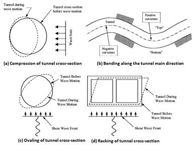
These potentially damaging scenarios can be intended as different deformations of the tunnel cross-section, as highlighted in Figure 2 for both square and circular shapes. Axial deformations in tunnels occur due to seismic wave components that run parallel to the tunnel axis, resulting in alternating compression and tension. Bending deformations, on the other hand, arise from seismic waves causing particle motions perpendicular to the tunnel's longitudinal axis.
Ovaling and racking deformations manifest in tunnel structures when shear waves propagate nearly normally to the tunnel axis, distorting the tunnel lining's cross-sectional shape. Diagonally propagating waves induce out-of-phase displacements across different sections of the structure, leading to the formation of a longitudinal compression/rarefaction wave. Typically, longer wavelengths correspond to larger displacement amplitudes, whereas shorter wavelengths with relatively small displacement amplitudes result in maximum curvatures.
As already mentioned multiple times, different ground conditions will result in different risk levels. In this sense, [29] and [30] explored the effects of depth on seismic response using scaled-down laboratory experiments and numerical simulations for square and circular tunnels. Additionally, [31] compiled empirical findings for various tunnel types and soil conditions.
Importantly, underwater tunnels in soft soils are particularly vulnerable to failure since loose water-saturated soil can experience liquefaction. This will be a major aspect dealt with in the remainder of this paper. Other reasons are speculated for their lower seismic robustness and resilience when compared to the deep tunnels [32]. For instance, the earthquake waves are amplified within soft superficial strata. Furthermore, the amplitude of seismically induced stress generally reaches a maximum close to the ground surface, where the ground accelerations are higher [31-33], while decaying with the depth [34-35]. Conversely, deep-buried infrastructures, especially flexible ones, are not expected to oscillate independently of the surrounding ground. Therefore, there is no amplification of the ground motion; only direct ground failure or relative displacements (as mentioned, e.g. along an active fault line) will cause structural damage.
However, it is important to remark once more that, due to the relative rarity of tunnel-damaging earthquake events, the available information is based on a scarce dataset of known case histories. These include, for instance, the aftermaths of the following earthquakes: San Francisco 1906 [25], Kanto 1923 [36], Hsinchu-Taichung 1935 [37], Kern Country 1952 [38], Hyogoken-Nanbu 1995 [39], Chi-Chi 1999 [37], [40], Duzce 1999 [41], Niigataken-Chuetu 2005 and Niigataken Chuetu-Oki 2007 [42], Wenchuan 2008 [43-45],Tohuku 2011 [46], Northern Aegean 2014 [47], and a few others [48] [49-50]. As of the writing of this article, Taiwan was hit by the strongest tremor in 25 years (Mw = 7.4 Hualien, April 3rd 2024). According to the most updated data, at least 75 roads and tunnels were damaged and several totally or partially collapsed in Hualien County, leaving at least 200+ people stranded inside.

Not only that but most experimental data about strong ground motions are derived from recordings collected from instrumented stations located in urban areas (relatively low topography areas) and at shallow depths. Therefore, their applicability or transferability to deep tunnels bored in rock, with very different topographic and stratigraphic amplification factors, is affected by uncertainties. In conclusion, Figure 3 briefly recapitulates the main expected mechanism failures for above- and below-ground rail and road infrastructures.
3. Case studies
Here, the seismic responses of one underwater rail tunnel and two mountain road tunnels to the same seismic event are considered. These tunnels represent examples of 'Cut-and-Cover' (BART) versus 'Bored/Drilled' (Caldecott) underground structures, known to exhibit different behaviours under similar seismic conditions [52].
This study considers the aftermath of the Mw=4.4 Berkeley Earthquake of January 4th, 2018, for which further documentation can be found in [53].
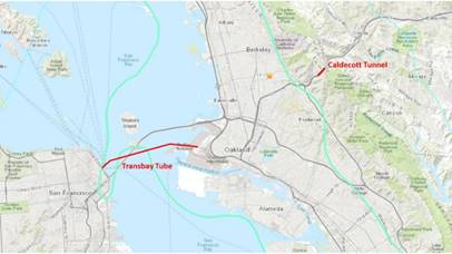
All case studies are located near San Francisco and Oakland, CA, USA. The data used in this study were retrieved from the Center for Engineering Strong Motion Data (CESMD) database, specifically referring to the stations CE58359 for Caldecott Bore 3, CE58540 for Caldecott Bore 4, and CE58580 for the Transbay Tube.
As stated previously, the cross-sectional deformations play a key role in the seismic response of underground tunnels; hence, for consistency and due to the specific orientation and location of the three case studies with respect to the epicentre (see Figure 4), only transversal recording channels have been considered, as it will be detailed later in more detail.
3. 1. Bay Area Rapid Transit (BART) Transbay Tube
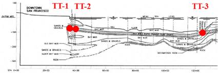
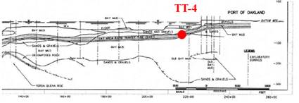
The BART system, established in 1969, was among the earliest underground facilities to incorporate seismic considerations into its design. Spanning below the San Francisco Bay East to West, it reaches a maximum depth of -41 meters below sea level and spans a distance of 5.8 kilometres. It comprises underground stations and tunnels situated in fill and soft Bay Mud deposits (Figure 5). It was built using the immersion tube technique, where a trench was excavated in the bay muck and the prefabricated tubular steel and reinforced concrete segment were first immersed adopting construction barges and then covered with a layer of rock, sand, and gravel.
(a)
(b)
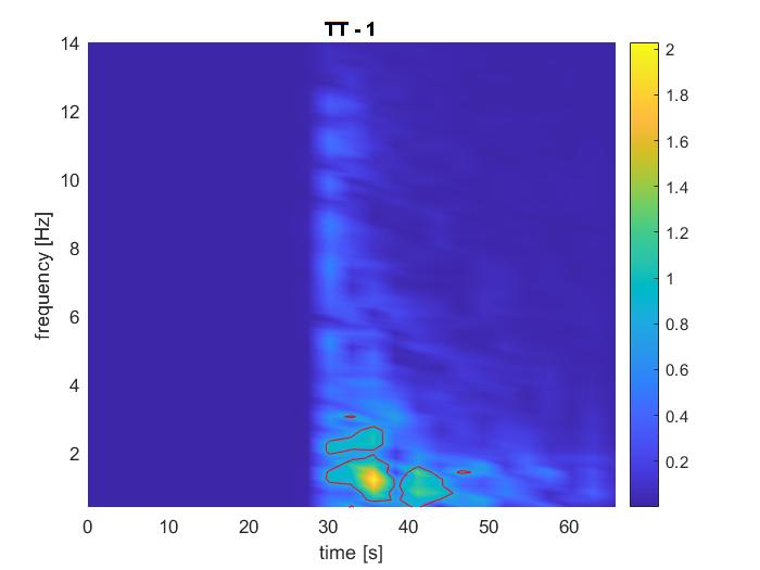
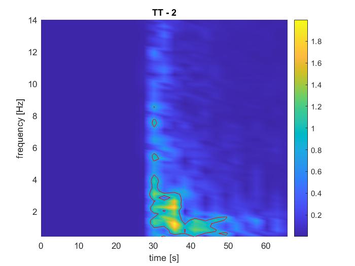
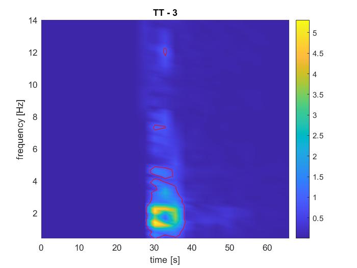
Remarkably, during the Loma Prieta 1989 Earthquake, the BART infrastructure remained unscathed and operated continuously for 24 hours post-earthquake. This resilience can be attributed to its design with stringent seismic standards. Specifically, special seismic joints were integrated, as detailed by Bickel and Tanner in 1982 [54], to accommodate varying movements at ventilation structures. The system was engineered to withstand earth and water loads while maintaining watertight connections and staying within permissible differential movements. Despite lacking precise data on the extent of movement during the earthquake, no damage was detected at these adaptable joints [28]. For the sake of this research, the four channels TT-1 (San Francisco entrance, West of the seismic sliding joint), TT-2 (East of the joint), TT-3 (close to Yerba Buena Island), and TT-4 (Oakland entrance), as depicted in Figure 4.a and 4.b, were considered. Further details on this case study, its structural components, and the surrounding geological conditions can be found in previous works from the Authors [1], [17] as well as in [55].
3. 2. Caldecott Tunnel’s Bore 3 and 4
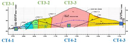
The Caldecott Tunnel is an extensive underground passageway that traverses the Berkeley Hills, linking Oakland and Orinda, situated within a geological zone characterized by marine and non-marine sedimentary rocks like sandstone and claystone. Notably, the tunnel intersects four significant inactive faults, perpendicular to its alignment, as shown in Figure 6.
This infrastructure comprises four separate bores, constructed at different points in time to accommodate the growing vehicular traffic between the San Francisco Bay Area and Central California. Initially, Bores 1 and 2 were operational upon the tunnel's opening in 1937. Subsequently, Bore 3 was added in 1964, and Bore 4, excavated with the New Austrian Tunnelling Method (NATM), commenced service in 2013. The latest tunnels, namely Bore 3 and 4, are both outfitted with SHM systems. Bore 3 has instrumentation in three cross-sections (indicated in green in Figure 6), while Bore 4 is equipped with 21 sensors positioned at five distinct cross-sections. For this study, the channels indicated as CT3-1, CT3-2, CT3-3 and CT4-1, CT4-2, CT4-3 were selected.
Importantly, following Caltrans' standard protocol for "critical" structures along key transportation corridors, the seismic design of Bore 4 was based on the Safety Evaluation Earthquake (SEE), which accounted for a seismic event with a return period of 1,500 years for the design process. These aspects are discussed in more detail in [57]. Further details about the excavation and structural configurations can be found in[1], [17] as well as in [58-59].
Again, for more details on this case study, interested readers can refer to [1] and, for Bore 4 specifically, to [58-59].
4. Time-Frequency Analysis of the Seismic Response
This and the following Section report the two sets of results achieved by this comparative analysis.
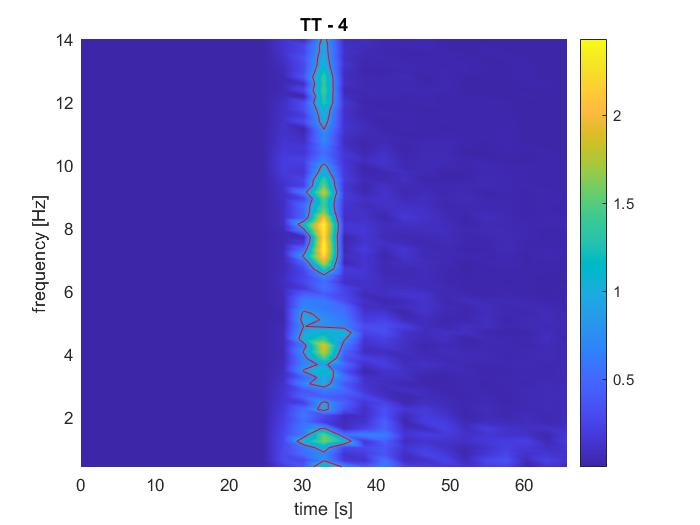
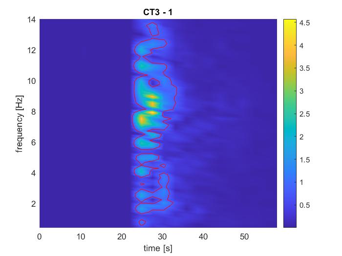
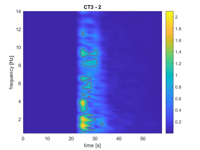
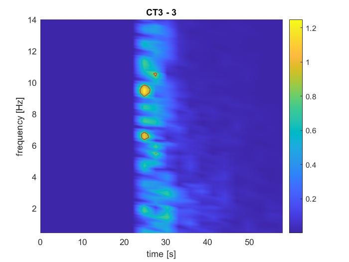
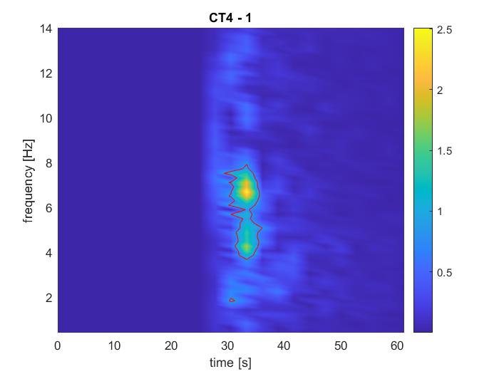
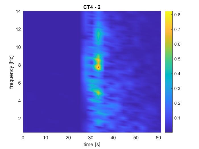
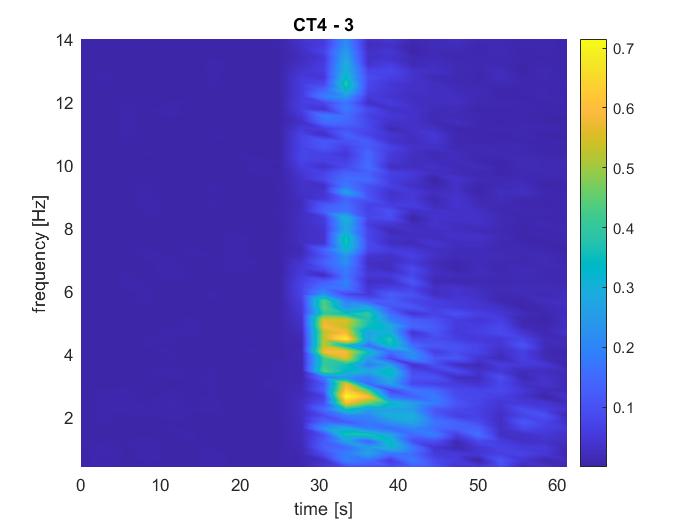
To generate the spectrograms reported in Figures 7 and 8, the frequency spectra were partitioned into 5-second intervals with a 2.5-second overlap (50% overlap). Baseline correction and a Tukey window with a parameter of r=5% were applied within each interval. Subsequently, the windowed signals underwent the Fast Fourier Transform, and the resulting spectra were smoothed using a 5-point half-width moving average.
 (a) |
 (b) |
 (c) |
 (d) |
These time-frequency domain analyses enable to see more clearly how the duration of the recording in all the Transbay Tube and the Caldecott Tunnel Bore 3 is included in a 10-s-long range. For Bore 4, the duration is slightly longer at the lower frequencies, even if there is a less marked transition and it is not as well-defined as in the two other cases. On the other hand, the frequency content is variable, considering the three different infrastructures, but also considering different channels of the same structure. However, in all cases is always mainly contained under 15 Hz (much less for most of the channels along the Transbay Tube). Another distinction between the cases is the amplitude behaviours. For instance, the amplitude of some channels of the Transbay Tube decreases way faster than in other ones; yet, all of them dissipate slower than Bore 3 in the Caldecott Tunnel.
 (a) |
 (b) |
 (c) |
 (d) |
 (e) |
 (f) |
5. Arias Intensity and Significant Duration
Following the example of [47], Arias Intensity (AI) is here used to investigate the underwater/underground infrastructures’ response to strong motions. The standard definition of AI, as introduced by [61], and expressed in terms of [m/s], is:
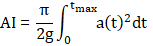
Where g is the acceleration of gravity, tmax is the maximum duration of the recorded signal, and a(t)2 is the quadratic acceleration at time t. The meaning offered by this formulation is as the cumulative energy per unit weight absorbed by an infinite set of undamped single-degree-of-freedom oscillators having a uniform distribution of fundamental frequencies on (0,∞). In this sense, AI is a function of the time-varying ground acceleration amplitude, the frequency content (since the value of the integrand between zero-crossing will be frequency-dependent), and the duration of the ground motion. These three factors are widely considered to be directly related to the seismic risk related to a given event [62]. For this reason, AI measures have been proven to be strongly correlated to various metrics of seismic response, also in the specific case of bridges [63].
Another important parameter is the so-called significant duration, Ds595, defined as the time elapsed in between the two instants when 5% and 95% of the total energy ∫otmaxa(t)2dt is reached [64].
Both AI and Ds595 are reported in Table 1. As main observations, for the Transbay Tube, Ds595 slightly increases as the sensor location is located farther from the epicentre. For the two bores of the Caldecott Tunnel, the main difference is related to the significant durations. The ones of Bore 3 are between 2.3 and 3.6 seconds, whereas the Ds595of Bore 4 is between 8.4 and 13.4 seconds. The significant duration of the Transbay Tube varies along its length, showing different durations at the extremities. Particularly, the channels belonging to the East part of the Tube (chan. TT-3 and TT-4), which are closer to the epicentre, exhibit a duration below 10 seconds. The ones located in the West part (chan. TT-1 and TT-2) exhibit Ds595≅16 s. However, this was largely expected due to geometric attenuation, that is to say, the distance from the epicentre of the quake implies a large build-up and therefore it increases the significant seismic duration.
AI values of the Transbay Tube are generally one order of magnitude higher than the ones of the bored tunnels. Comparing the AIs of the two rock tunnels, it is possible to denote that both have the same order of magnitude, but the ones of Bore 4 are typically smaller. The data show the lower seismic vulnerability of the rock tunnels (i.e. the Caldecott Tunnel Bore 3 and 4) in comparison to the one built in soft soil (i.e. Transbay Tube). Additional conclusions cannot be derived about the vulnerability of the two bore tunnels (i.e. which one is at major risk).
Table 1. Significant duration and Arias Intensity of the selected output channels.
|
Chan. |
Ds595 |
AI [m/s] |
Chan. |
Ds595 |
AI [m/s] |
|
TT-1 |
16.44 |
0.0017 |
CT3-2 |
3.62 |
9.8e-4 |
|
TT-2 |
15.94 |
0.0029 |
CT3-3 |
2.58 |
6.2e-4 |
|
TT-3 |
2.37 |
0.0094 |
CT4-1 |
8.41 |
2.9e-4 |
|
TT-4 |
8.25 |
0.0021 |
CT4-2 |
10.41 |
1.0e-4 |
|
CT3-1 |
2.36 |
0.0049 |
CT4-3 |
13.46 |
6.9e-5 |
6. Conclusion
The results of this research work should be considered in the context of both well-established and more recent studies. All the current scientific literature corroborates that both shallow tunnels in soft ground and deep tunnels in hard rock are generally safer than above-ground structures, albeit not entirely earthquake-proof. Yet, more important for the aims of this study, deep tunnels in hard rock generally are expected to exhibit greater safety, compared to shallow ones in soft and water-saturated soil.
Currently, the general consensus is that this depends on geotechnical and geological factors. In fact, the dynamic behaviour of man-made tunnels varies significantly based on the surrounding geological conditions. Tunnels in shallow depths within soft soils are more susceptible to earthquake loads due to kinematic loading induced by surrounding materials with varying stiffness and amplification effects. In contrast, tunnels bored through dense soil or hard rock are generally more resilient. However, until this moment, these assumptions were not assessed in nearby infrastructures undergoing the same seismic event.
Here, the differences in Arias Intensity and its build-up over time are proposed as a potential proof and explanation for these phenomena, alongside the obvious presence of liquefaction and related problems. These experimental pieces of evidence, collected from a near-fault earthquake at three stations, are consistent with the established interpretation of stratigraphic seismic amplification. These findings will aid structural and geotechnical engineers in addressing the challenges of designing tunnels capable of withstanding seismic events in varying ground conditions.
References
[1] Dalmasso M., Civera M., De Biagi V., Surace C., and Chiaia B., "A Comparative Analysis of the Seismic Response of a Nearby Tunnel and Bridge," in 8th World Conference on Earthquake Engineering (WCEE2024) - accepted for publication, 2024.
[2] D. Mccallen, A. Astaneh-Asl, S. Larsen, and L. Hutchings, "Dynamic Response of the Suspension Spans of the San Francisco-Oakland Bay Bridge," in 8th U.S. National Conference on Earthquake Engineering, 2006.
[3] J. C. Wilson, "Analysis of the observed seismic response of a highway bridge," Earthq Eng Struct Dyn, vol. 14, no. 3, pp. 339-354, May 1986, doi: 10.1002/eqe.4290140303.
View Article
[4] D. M. Siringoringo, Y. Fujino, and K. Namikawa, "Seismic Response Analyses of the Yokohama Bay Cable-Stayed Bridge in the 2011 Great East Japan Earthquake," Journal of Bridge Engineering, vol. 19, no. 8, Aug. 2014, doi: 10.1061/(ASCE)BE.1943-5592.0000508.
View Article
[5] L. Jiang, J. Zhong, and W. Yuan, "The pulse effect on the isolation device optimization of simply supported bridges in near-fault regions," Structures, vol. 27, pp. 853-867, Oct. 2020, doi: 10.1016/j.istruc.2020.06.034.
View Article
[6] J. Zhang and N. Makris, "Seismic response analysis of highway overcrossings including soil-structure interaction," Earthq Eng Struct Dyn, vol. 31, no. 11, pp. 1967-1991, Nov. 2002, doi: 10.1002/eqe.197.
View Article
[7] E. Tubaldi, L. Tassotti, A. Dall'Asta, and L. Dezi, "Seismic response analysis of slender bridge piers," Earthq Eng Struct Dyn, vol. 43, no. 10, pp. 1503-1519, Aug. 2014, doi: 10.1002/eqe.2408.
View Article
[8] J. C. Wilson and B. S. Tan, "Bridge Abutments: Formulation of Simple Model for Earthquake Response Analysis," J Eng Mech, vol. 116, no. 8, pp. 1828-1837, Aug. 1990, doi: 10.1061/(ASCE)0733-9399(1990)116:8(1828).
View Article
[9] A. Camara and E. Efthymiou, "Deck-tower interaction in the transverse seismic response of cable-stayed bridges and optimum configurations," Eng Struct, vol. 124, pp. 494-506, Oct. 2016, doi: 10.1016/j.engstruct.2016.06.017.
View Article
[10] J. Yi Meng and E. M. Lui, "Seismic analysis and assessment of a skew highway bridge," Eng Struct, vol. 22, no. 11, pp. 1433-1452, Nov. 2000, doi: 10.1016/S0141-0296(99)00097-8.
View Article
[11] J. Yang and C. M. Lee, "Characteristics of vertical and horizontal ground motions recorded during the Niigata-ken Chuetsu, Japan Earthquake of 23 October 2004," Eng Geol, vol. 94, no. 1-2, pp. 50-64, Oct. 2007, doi: 10.1016/j.enggeo.2007.06.003.
View Article
[12] S. K. Kunnath, E. Erduran, Y. H. Chai, and M. Yashinsky, "Effect of Near-Fault Vertical Ground Motions on Seismic Response of Highway Overcrossings," Journal of Bridge Engineering, vol. 13, no. 3, pp. 282-290, May 2008, doi: 10.1061/(ASCE)1084-0702(2008)13:3(282).
View Article
[13] L. Deng, W. Wang, and Y. Yu, "State-of-the-Art Review on the Causes and Mechanisms of Bridge Collapse," Journal of Performance of Constructed Facilities, vol. 30, no. 2, Apr. 2016, doi: 10.1061/(ASCE)CF.1943-5509.0000731.
View Article
[14] K. Kawashima and I. Buckle, "Structural Performance of Bridges in the Tohoku-Oki Earthquake," Earthquake Spectra, vol. 29, no. 1_suppl, pp. 315-338, Mar. 2013, doi: 10.1193/1.4000129.
View Article
[15] D. Mitchell, S. Huffman,R. Tremblay, M. Saatcioglu, D. Palermo, R. Tinawi, D. Lau., "Damage to bridges due to the 27 February 2010 Chile earthquake," Canadian Journal of Civil Engineering, vol. 40, no. 8, pp. 675-692, Aug. 2013, doi: 10.1139/l2012-045.
View Article
[16] A. Vlašić, M. Srbić, D. Skokandić, and A. Mandić Ivanković, "Post-Earthquake Rapid Damage Assessment of Road Bridges in Glina County," Buildings, vol. 12, no. 1, p. 42, Jan. 2022, doi: 10.3390/buildings12010042.
View Article
[17] Dalmasso M., Civera M., De Biagi V., Surace C., and Chiaia B., "Conditional generative adversarial networks for the data augmentation and seismic analysis of above and underground infrastructures," Tunnelling and Underground Space Technology - under review.
[18] M. Abbas, K. Elbaz, S.-L. Shen, and J. Chen, "Earthquake effects on civil engineering structures and perspective mitigation solutions: a review," Arabian Journal of Geosciences, vol. 14, no. 14, p. 1350, Jul. 2021, doi: 10.1007/s12517-021-07664-5.
View Article
[19] W. P. Yen, G. Chen, M. Yashinski, Y. Hashash, C. Holub, K. Wang, X. Guo, "Lessons in bridge damage learned from the Wenchuan earthquake," Earthquake Engineering and Engineering Vibration, vol. 8, no. 2, pp. 275-285, Jun. 2009, doi: 10.1007/S11803-009-9064-X
View Article
[20] Y. Chen, J. Hu, and F. Peng, "Seismological challenges in earthquake hazard reductions: reflections on the 2008 Wenchuan earthquake," Sci Bull (Beijing), vol. 63, no. 17, pp. 1159-1166, Sep. 2018, doi: 10.1016/J.SCIB.2018.06.015.
View Article
[21] L. Jiang, X. Kang, C. Li, and G. Shao, "Earthquake response of continuous girder bridge for high-speed railway: A shaking table test study," Eng Struct, vol. 180, pp. 249-263, Feb. 2019, doi: 10.1016/J.ENGSTRUCT.2018.11.047.
View Article
[22] S. A. Argyroudis, S. Α. Mitoulis, M. G. Winter, and A. M. Kaynia, "Fragility of transport assets exposed to multiple hazards: State-of-the-art review toward infrastructural resilience," Reliab Eng Syst Saf, vol. 191, p. 106567, Nov. 2019, doi: 10.1016/j.ress.2019.106567.
View Article
[23] A. Kaynia, J. Mayoral, J. Johansson, S. Argyroudis, K. Pitilakis, and A. Anastasiadis, "Fragility functions for roadway system elements," 2011.
[24] Z. Z. Wang and Z. Zhang, "Seismic damage classification and risk assessment of mountain tunnels with a validation for the 2008 Wenchuan earthquake," Soil Dynamics and Earthquake Engineering, vol. 45, pp. 45-55, Feb. 2013, doi: 10.1016/j.soildyn.2012.11.002.
View Article
[25] C. Prentice and D. Ponti, "Coseismic deformation of the Wrights tunnel during the 1906 San Francisco earthquake: A key to understanding 1906 fault slip and 1989 surface ruptures in the southern Santa Cruz Mountains, California," Journal of Geophysical Research, 1997.
View Article
[26] G. Cui and J. Ma, "Shaking table test on the seismic response of the portal section in soft and hard rock junction," Sci Prog, vol. 104, no. 3, p. 003685042110313, Jul. 2021, doi: 10.1177/00368504211031393.
[27] G. N. Owen and R. E. Scholl, "Earthquake engineering of large underground structures," Federal Highway Administration and National Science Foundation, 1981.
[28] Y. M. A. Hashash, J. J. Hook, B. Schmidt, and J. I-Chiang Yao, "Seismic design and analysis of underground structures," Tunnelling and Underground Space Technology, vol. 16, no. 4, pp. 247-293, Oct. 2001, doi: 10.1016/S0886-7798(01)00051-7.
View Article
[29] U. Cilingir and S. P. G. Madabhushi, "Effect of Depth on the Seismic Response of Square Tunnels," Soils and Foundations, vol. 51, no. 3, pp. 449-457, Jun. 2011, doi: 10.3208/sandf.51.449.
View Article
[30] U. Cilingir and S. P. G. Madabhushi, "Effect of depth on seismic response of circular tunnels," Canadian Geotechnical Journal, vol. 48, no. 1, pp. 117-127, Jan. 2011, doi: 10.1139/T10-047.
View Article
[31] G. Tsinidis, F. de Silva, I. Anastasopoulos, E. Bilotta, A. Bobet, Y. M.A. Hashash, C. He, G. Kampas, J. Knappett, G. Madabhushi, N. Nikitas, K. Pitilakis, F. Silvestri, G. Viggiani, R. Fuentes, "Seismic behaviour of tunnels: From experiments to analysis," Tunnelling and Underground Space Technology, vol. 99, p. 103334, May 2020, doi: 10.1016/j.tust.2020.103334.
View Article
[32] G. Andreotti, and C. Lai. "Seismic vulnerability of deep tunnels: numerical modeling for a fully nonlinear dynamic analysis." In 2ECEES (Second European Conference on Earthquake Engineering and Seismology), Istanbul, Turkey. 2014.
[33] Okamoto S., Introduction To Earthquake Engineering. 1984.
[34] Steven Lawrence Kramer, Geotechnical Earthquake Engineering. 1996.
[35] S. P. G. Madabhushi and X. Zeng, "Seismic response of flexible cantilever retaining walls with dry backfill," Geomechanics and Geoengineering, vol. 1, no. 4, pp. 275-289, Dec. 2006, doi: 10.1080/17486020601039170.
View Article
[36] Okamoto S., "Introduction to earthquake engineering," 1984.
[37] J.-H. Hwang and C.-C. Lu, "Seismic capacity assessment of old Sanyi railway tunnels," Tunnelling and Underground Space Technology, vol. 22, no. 4, pp. 433-449, Jul. 2007, doi: 10.1016/j.tust.2006.09.002.
View Article
[38] V. Kontogianni and S. Stiros, "Earthquakes and Seismic Faulting: Effects on Tunnels," TURKISH JOURNAL OF EARTH SCIENCES, vol. 12, 2003.
[39] T. Asakura and Y. Sato, "Mountain tunnels damage in the 1995 Hyogoken-nanbu Earthquake.," Quarterly Report-RTRI 39 , 1998.
View Article
[40] W. L. Wang, T. T. Wang, J. J. Su, C. H. Lin, C. R. Seng, and T. H. Huang, "Assessment of damage in mountain tunnels due to the Taiwan Chi-Chi Earthquake," Tunnelling and Underground Space Technology, vol. 16, no. 3, pp. 133-150, Jul. 2001, doi: 10.1016/S0886-7798(01)00047-5.
View Article
[41] H. S. Akyu¨z, R. Hartleb; A. Barka; E. Altunel; G. Sunal; B. Meyer; R. Armijo, "Surface Rupture and Slip Distribution of the 12 November 1999 Duzce Earthquake (M 7.1), North Anatolian Fault, Bolu, Turkey," Bulletin of the Seismological Society of America, vol. 92, pp. 61-66, Feb. 2002.
View Article
[42] C.-H. Chen, T.-T. Wang, F.-S. Jeng, and T.-H. Huang, "Mechanisms causing seismic damage of tunnels at different depths," Tunnelling and Underground Space Technology, vol. 28, pp. 31-40, Mar. 2012, doi: 10.1016/j.tust.2011.09.001.
View Article
[43] H. Yu, J. Chen, Y. Yuan, and X. Zhao, "Seismic damage of mountain tunnels during the 5.12 Wenchuan earthquake," J Mt Sci, vol. 13, no. 11, pp. 1958-1972, Nov. 2016, doi: 10.1007/s11629-016-3878-6.
View Article
[44] H. Yu, J. Chen, A. Bobet, and Y. Yuan, "Damage observation and assessment of the Longxi tunnel during the Wenchuan earthquake," Tunnelling and Underground Space Technology, vol. 54, pp. 102-116, Apr. 2016, doi: 10.1016/j.tust.2016.02.008.
View Article
[45] C. A. Jaramillo, "Impact of seismic design on tunnels in rock - Case histories," Underground Space, vol. 2, no. 2, pp. 106-114, Jun. 2017, doi: 10.1016/j.undsp.2017.03.004.
View Article
[46] T. Kosugi, T. Hatsuku, and M. Shimonishi, "Examples of bridge damage on metropolitan expressway discovered by emergency structural inspections after the Tohoku Earthquake."
[47] S. U. Dikmen, "Response of Marmaray Submerged Tunnel during 2014 Northern Aegean Earthquake (Mw=6.9)," Soil Dynamics and Earthquake Engineering, vol. 90, pp. 15-31, Nov. 2016, doi: 10.1016/j.soildyn.2016.08.006.
View Article
[48] G. Tsinidis, E. Rovithis, K. Pitilakis, and J. L. Chazelas, "Seismic response of box-type tunnels in soft soil: Experimental and numerical investigation," Tunnelling and Underground Space Technology, vol. 59, pp. 199-214, Oct. 2016, doi: 10.1016/j.tust.2016.07.008.
View Article
[49] Charles H. Dowding and Arnon Rozan, "DAMAGE TO ROCK TUNNELS FROM EARTHQUAKE SHAKING," ournal of the Geotechnical Engineering Division, pp. 175-191, 1978.
View Article
[50] S. Sharma and W. R. Judd, "Underground opening damage from earthquakes," Eng Geol, vol. 30, no. 3-4, pp. 263-276, Jun. 1991, doi: 10.1016/0013-7952(91)90063-Q.
View Article
[51] A. M. El-Maissi, S. A. Argyroudis, and F. M. Nazri, "Seismic Vulnerability Assessment Methodologies for Roadway Assets and Networks: A State-of-the-Art Review," Sustainability, vol. 13, no. 1, p. 61, Dec. 2020, doi: 10.3390/su13010061.
View Article
[52] D. C. Department of Homeland Security Federal Emergency Management Agency Mitigation Division Washington, Hazus®-MH 2.1 - Technical Manual .
[53] C.E.S.M.D. Strong Motion Data Set, "Berkeley Earthquake of 04 Jan 2018," https://www.strongmotioncenter.org/cgi-bin/CESMD/iqr_dist_DM2.pl?IQRID=Berkeley_04Jan2018_72948801 - last accessed March 27th, 2024.
[54] J. O. Bickel and D. N. Tanner, "Sunken tube tunnels," Tunnel engineering handbook, 1982.
[55] Metropolitan Transportation Commission, "Core Capacity Transit Study (CCTS) Initial Engineering Study, Appendix A - Engineering Methodology, Environmental Engineering, and Permitting," 2015.
[56] Parsons Brinckerhoff Quade & Douglas, "Geologic Cross Section along the BART Transbay Tunnel, Engineering Geology of the Bay Area Rapid Transit (BART) System," 1965.
[57] C.-T. Yang, H. Law, and A. Shamsabadi, "Seismic Analyses for the Fourth Bore of Caldecott Tunnel," pp. 1-10, May 2008, doi: 10.1061/40975(318)208.
View Article
[56] Parsons Brinckerhoff Quade & Douglas, "Geologic Cross Section along the BART Transbay Tunnel, Engineering Geology of the Bay Area Rapid Transit (BART) System," 1965.
[58] P. Wilson, A. Shamsabadi, and H. Law, "Site-Specific Seismic Coefficients for Retaining Wall/Slope Design: Fourth Bore Caldecott Tunnel," in Tenth U.S. Conference on Earthquake Engineering, Anchorage, Jul. 2014.
[59] B. Thapa, A. Nitschke, I. Ramirez, M. McRae, and V. Gall, "Lessons Learned from NATM Design and Construction of the Caldecott Fourth Bore," 2013.
[60] Jacobs Associates, "Caldecott Improvement Project - Geotechnical Baseline Report," 2009.
[61] A. Arias, "A measure of earthquake intensity," Seismic Design for Nuclear Power Plants, pp. 438-483, 1970.
[62] B. A. Bradley, "Correlation of Arias intensity with amplitude, duration and cumulative intensity measures," Soil Dynamics and Earthquake Engineering, vol. 78, pp. 89-98, Nov. 2015, doi: 10.1016/J.SOILDYN.2015.07.009.
View Article
[63] K. Mackie and B. Stojadinović, "Probabilistic Seismic Demand Model for California Highway Bridges," Journal of Bridge Engineering, vol. 6, no. 6, pp. 468-481, Dec. 2001, doi: 10.1061/(ASCE)1084-0702(2001)6:6(468).
View Article
[64] M. D. Trifunac and A. G. Brady, "A study on the duration of strong earthquake ground motion," Bulletin of the Seismological Society of America, vol. 65, no. 3, pp. 581-626, Jun. 1975, doi: 10.1785/BSSA0650030581.
[1] Dalmasso M., Civera M., De Biagi V., Surace C., and Chiaia B., "A Comparative Analysis of the Seismic Response of a Nearby Tunnel and Bridge," in 8th World Conference on Earthquake Engineering (WCEE2024) - accepted for publication, 2024.
[2] D. Mccallen, A. Astaneh-Asl, S. Larsen, and L. Hutchings, "Dynamic Response of the Suspension Spans of the San Francisco-Oakland Bay Bridge," in 8th U.S. National Conference on Earthquake Engineering, 2006.
[3] J. C. Wilson, "Analysis of the observed seismic response of a highway bridge," Earthq Eng Struct Dyn, vol. 14, no. 3, pp. 339-354, May 1986, doi: 10.1002/eqe.4290140303. View Article
[4] D. M. Siringoringo, Y. Fujino, and K. Namikawa, "Seismic Response Analyses of the Yokohama Bay Cable-Stayed Bridge in the 2011 Great East Japan Earthquake," Journal of Bridge Engineering, vol. 19, no. 8, Aug. 2014, doi: 10.1061/(ASCE)BE.1943-5592.0000508. View Article
[5] L. Jiang, J. Zhong, and W. Yuan, "The pulse effect on the isolation device optimization of simply supported bridges in near-fault regions," Structures, vol. 27, pp. 853-867, Oct. 2020, doi: 10.1016/j.istruc.2020.06.034. View Article
[6] J. Zhang and N. Makris, "Seismic response analysis of highway overcrossings including soil-structure interaction," Earthq Eng Struct Dyn, vol. 31, no. 11, pp. 1967-1991, Nov. 2002, doi: 10.1002/eqe.197. View Article
[7] E. Tubaldi, L. Tassotti, A. Dall'Asta, and L. Dezi, "Seismic response analysis of slender bridge piers," Earthq Eng Struct Dyn, vol. 43, no. 10, pp. 1503-1519, Aug. 2014, doi: 10.1002/eqe.2408. View Article
[8] J. C. Wilson and B. S. Tan, "Bridge Abutments: Formulation of Simple Model for Earthquake Response Analysis," J Eng Mech, vol. 116, no. 8, pp. 1828-1837, Aug. 1990, doi: 10.1061/(ASCE)0733-9399(1990)116:8(1828). View Article
[9] A. Camara and E. Efthymiou, "Deck-tower interaction in the transverse seismic response of cable-stayed bridges and optimum configurations," Eng Struct, vol. 124, pp. 494-506, Oct. 2016, doi: 10.1016/j.engstruct.2016.06.017. View Article
[10] J. Yi Meng and E. M. Lui, "Seismic analysis and assessment of a skew highway bridge," Eng Struct, vol. 22, no. 11, pp. 1433-1452, Nov. 2000, doi: 10.1016/S0141-0296(99)00097-8. View Article
[11] J. Yang and C. M. Lee, "Characteristics of vertical and horizontal ground motions recorded during the Niigata-ken Chuetsu, Japan Earthquake of 23 October 2004," Eng Geol, vol. 94, no. 1-2, pp. 50-64, Oct. 2007, doi: 10.1016/j.enggeo.2007.06.003. View Article
[12] S. K. Kunnath, E. Erduran, Y. H. Chai, and M. Yashinsky, "Effect of Near-Fault Vertical Ground Motions on Seismic Response of Highway Overcrossings," Journal of Bridge Engineering, vol. 13, no. 3, pp. 282-290, May 2008, doi: 10.1061/(ASCE)1084-0702(2008)13:3(282). View Article
[13] L. Deng, W. Wang, and Y. Yu, "State-of-the-Art Review on the Causes and Mechanisms of Bridge Collapse," Journal of Performance of Constructed Facilities, vol. 30, no. 2, Apr. 2016, doi: 10.1061/(ASCE)CF.1943-5509.0000731. View Article
[14] K. Kawashima and I. Buckle, "Structural Performance of Bridges in the Tohoku-Oki Earthquake," Earthquake Spectra, vol. 29, no. 1_suppl, pp. 315-338, Mar. 2013, doi: 10.1193/1.4000129. View Article
[15] D. Mitchell, S. Huffman,R. Tremblay, M. Saatcioglu, D. Palermo, R. Tinawi, D. Lau., "Damage to bridges due to the 27 February 2010 Chile earthquake," Canadian Journal of Civil Engineering, vol. 40, no. 8, pp. 675-692, Aug. 2013, doi: 10.1139/l2012-045. View Article
[16] A. Vlašić, M. Srbić, D. Skokandić, and A. Mandić Ivanković, "Post-Earthquake Rapid Damage Assessment of Road Bridges in Glina County," Buildings, vol. 12, no. 1, p. 42, Jan. 2022, doi: 10.3390/buildings12010042. View Article
[17] Dalmasso M., Civera M., De Biagi V., Surace C., and Chiaia B., "Conditional generative adversarial networks for the data augmentation and seismic analysis of above and underground infrastructures," Tunnelling and Underground Space Technology - under review.
[18] M. Abbas, K. Elbaz, S.-L. Shen, and J. Chen, "Earthquake effects on civil engineering structures and perspective mitigation solutions: a review," Arabian Journal of Geosciences, vol. 14, no. 14, p. 1350, Jul. 2021, doi: 10.1007/s12517-021-07664-5. View Article
[19] W. P. Yen, G. Chen, M. Yashinski, Y. Hashash, C. Holub, K. Wang, X. Guo, "Lessons in bridge damage learned from the Wenchuan earthquake," Earthquake Engineering and Engineering Vibration, vol. 8, no. 2, pp. 275-285, Jun. 2009, doi: 10.1007/S11803-009-9064-X View Article
[20] Y. Chen, J. Hu, and F. Peng, "Seismological challenges in earthquake hazard reductions: reflections on the 2008 Wenchuan earthquake," Sci Bull (Beijing), vol. 63, no. 17, pp. 1159-1166, Sep. 2018, doi: 10.1016/J.SCIB.2018.06.015. View Article
[21] L. Jiang, X. Kang, C. Li, and G. Shao, "Earthquake response of continuous girder bridge for high-speed railway: A shaking table test study," Eng Struct, vol. 180, pp. 249-263, Feb. 2019, doi: 10.1016/J.ENGSTRUCT.2018.11.047. View Article
[22] S. A. Argyroudis, S. Α. Mitoulis, M. G. Winter, and A. M. Kaynia, "Fragility of transport assets exposed to multiple hazards: State-of-the-art review toward infrastructural resilience," Reliab Eng Syst Saf, vol. 191, p. 106567, Nov. 2019, doi: 10.1016/j.ress.2019.106567. View Article
[23] A. Kaynia, J. Mayoral, J. Johansson, S. Argyroudis, K. Pitilakis, and A. Anastasiadis, "Fragility functions for roadway system elements," 2011.
[24] Z. Z. Wang and Z. Zhang, "Seismic damage classification and risk assessment of mountain tunnels with a validation for the 2008 Wenchuan earthquake," Soil Dynamics and Earthquake Engineering, vol. 45, pp. 45-55, Feb. 2013, doi: 10.1016/j.soildyn.2012.11.002. View Article
[25] C. Prentice and D. Ponti, "Coseismic deformation of the Wrights tunnel during the 1906 San Francisco earthquake: A key to understanding 1906 fault slip and 1989 surface ruptures in the southern Santa Cruz Mountains, California," Journal of Geophysical Research, 1997. View Article
[26] G. Cui and J. Ma, "Shaking table test on the seismic response of the portal section in soft and hard rock junction," Sci Prog, vol. 104, no. 3, p. 003685042110313, Jul. 2021, doi: 10.1177/00368504211031393.
[27] G. N. Owen and R. E. Scholl, "Earthquake engineering of large underground structures," Federal Highway Administration and National Science Foundation, 1981.
[28] Y. M. A. Hashash, J. J. Hook, B. Schmidt, and J. I-Chiang Yao, "Seismic design and analysis of underground structures," Tunnelling and Underground Space Technology, vol. 16, no. 4, pp. 247-293, Oct. 2001, doi: 10.1016/S0886-7798(01)00051-7. View Article
[29] U. Cilingir and S. P. G. Madabhushi, "Effect of Depth on the Seismic Response of Square Tunnels," Soils and Foundations, vol. 51, no. 3, pp. 449-457, Jun. 2011, doi: 10.3208/sandf.51.449. View Article
[30] U. Cilingir and S. P. G. Madabhushi, "Effect of depth on seismic response of circular tunnels," Canadian Geotechnical Journal, vol. 48, no. 1, pp. 117-127, Jan. 2011, doi: 10.1139/T10-047. View Article
[31] G. Tsinidis, F. de Silva, I. Anastasopoulos, E. Bilotta, A. Bobet, Y. M.A. Hashash, C. He, G. Kampas, J. Knappett, G. Madabhushi, N. Nikitas, K. Pitilakis, F. Silvestri, G. Viggiani, R. Fuentes, "Seismic behaviour of tunnels: From experiments to analysis," Tunnelling and Underground Space Technology, vol. 99, p. 103334, May 2020, doi: 10.1016/j.tust.2020.103334. View Article
[32] G. Andreotti, and C. Lai. "Seismic vulnerability of deep tunnels: numerical modeling for a fully nonlinear dynamic analysis." In 2ECEES (Second European Conference on Earthquake Engineering and Seismology), Istanbul, Turkey. 2014.
[33] Okamoto S., Introduction To Earthquake Engineering. 1984.
[34] Steven Lawrence Kramer, Geotechnical Earthquake Engineering. 1996.
[35] S. P. G. Madabhushi and X. Zeng, "Seismic response of flexible cantilever retaining walls with dry backfill," Geomechanics and Geoengineering, vol. 1, no. 4, pp. 275-289, Dec. 2006, doi: 10.1080/17486020601039170. View Article
[36] Okamoto S., "Introduction to earthquake engineering," 1984.
[37] J.-H. Hwang and C.-C. Lu, "Seismic capacity assessment of old Sanyi railway tunnels," Tunnelling and Underground Space Technology, vol. 22, no. 4, pp. 433-449, Jul. 2007, doi: 10.1016/j.tust.2006.09.002. View Article
[38] V. Kontogianni and S. Stiros, "Earthquakes and Seismic Faulting: Effects on Tunnels," TURKISH JOURNAL OF EARTH SCIENCES, vol. 12, 2003.
[39] T. Asakura and Y. Sato, "Mountain tunnels damage in the 1995 Hyogoken-nanbu Earthquake.," Quarterly Report-RTRI 39 , 1998. View Article
[40] W. L. Wang, T. T. Wang, J. J. Su, C. H. Lin, C. R. Seng, and T. H. Huang, "Assessment of damage in mountain tunnels due to the Taiwan Chi-Chi Earthquake," Tunnelling and Underground Space Technology, vol. 16, no. 3, pp. 133-150, Jul. 2001, doi: 10.1016/S0886-7798(01)00047-5. View Article
[41] H. S. Akyu¨z, R. Hartleb; A. Barka; E. Altunel; G. Sunal; B. Meyer; R. Armijo, "Surface Rupture and Slip Distribution of the 12 November 1999 Duzce Earthquake (M 7.1), North Anatolian Fault, Bolu, Turkey," Bulletin of the Seismological Society of America, vol. 92, pp. 61-66, Feb. 2002. View Article
[42] C.-H. Chen, T.-T. Wang, F.-S. Jeng, and T.-H. Huang, "Mechanisms causing seismic damage of tunnels at different depths," Tunnelling and Underground Space Technology, vol. 28, pp. 31-40, Mar. 2012, doi: 10.1016/j.tust.2011.09.001. View Article
[43] H. Yu, J. Chen, Y. Yuan, and X. Zhao, "Seismic damage of mountain tunnels during the 5.12 Wenchuan earthquake," J Mt Sci, vol. 13, no. 11, pp. 1958-1972, Nov. 2016, doi: 10.1007/s11629-016-3878-6. View Article
[44] H. Yu, J. Chen, A. Bobet, and Y. Yuan, "Damage observation and assessment of the Longxi tunnel during the Wenchuan earthquake," Tunnelling and Underground Space Technology, vol. 54, pp. 102-116, Apr. 2016, doi: 10.1016/j.tust.2016.02.008. View Article
[45] C. A. Jaramillo, "Impact of seismic design on tunnels in rock - Case histories," Underground Space, vol. 2, no. 2, pp. 106-114, Jun. 2017, doi: 10.1016/j.undsp.2017.03.004. View Article
[46] T. Kosugi, T. Hatsuku, and M. Shimonishi, "Examples of bridge damage on metropolitan expressway discovered by emergency structural inspections after the Tohoku Earthquake."
[47] S. U. Dikmen, "Response of Marmaray Submerged Tunnel during 2014 Northern Aegean Earthquake (Mw=6.9)," Soil Dynamics and Earthquake Engineering, vol. 90, pp. 15-31, Nov. 2016, doi: 10.1016/j.soildyn.2016.08.006. View Article
[48] G. Tsinidis, E. Rovithis, K. Pitilakis, and J. L. Chazelas, "Seismic response of box-type tunnels in soft soil: Experimental and numerical investigation," Tunnelling and Underground Space Technology, vol. 59, pp. 199-214, Oct. 2016, doi: 10.1016/j.tust.2016.07.008. View Article
[49] Charles H. Dowding and Arnon Rozan, "DAMAGE TO ROCK TUNNELS FROM EARTHQUAKE SHAKING," ournal of the Geotechnical Engineering Division, pp. 175-191, 1978. View Article
[50] S. Sharma and W. R. Judd, "Underground opening damage from earthquakes," Eng Geol, vol. 30, no. 3-4, pp. 263-276, Jun. 1991, doi: 10.1016/0013-7952(91)90063-Q. View Article
[51] A. M. El-Maissi, S. A. Argyroudis, and F. M. Nazri, "Seismic Vulnerability Assessment Methodologies for Roadway Assets and Networks: A State-of-the-Art Review," Sustainability, vol. 13, no. 1, p. 61, Dec. 2020, doi: 10.3390/su13010061. View Article
[52] D. C. Department of Homeland Security Federal Emergency Management Agency Mitigation Division Washington, Hazus®-MH 2.1 - Technical Manual .
[53] C.E.S.M.D. Strong Motion Data Set, "Berkeley Earthquake of 04 Jan 2018," https://www.strongmotioncenter.org/cgi-bin/CESMD/iqr_dist_DM2.pl?IQRID=Berkeley_04Jan2018_72948801 - last accessed March 27th, 2024.
[54] J. O. Bickel and D. N. Tanner, "Sunken tube tunnels," Tunnel engineering handbook, 1982.
[55] Metropolitan Transportation Commission, "Core Capacity Transit Study (CCTS) Initial Engineering Study, Appendix A - Engineering Methodology, Environmental Engineering, and Permitting," 2015.
[56] Parsons Brinckerhoff Quade & Douglas, "Geologic Cross Section along the BART Transbay Tunnel, Engineering Geology of the Bay Area Rapid Transit (BART) System," 1965.
[57] C.-T. Yang, H. Law, and A. Shamsabadi, "Seismic Analyses for the Fourth Bore of Caldecott Tunnel," pp. 1-10, May 2008, doi: 10.1061/40975(318)208. View Article
[56] Parsons Brinckerhoff Quade & Douglas, "Geologic Cross Section along the BART Transbay Tunnel, Engineering Geology of the Bay Area Rapid Transit (BART) System," 1965.
[58] P. Wilson, A. Shamsabadi, and H. Law, "Site-Specific Seismic Coefficients for Retaining Wall/Slope Design: Fourth Bore Caldecott Tunnel," in Tenth U.S. Conference on Earthquake Engineering, Anchorage, Jul. 2014.
[59] B. Thapa, A. Nitschke, I. Ramirez, M. McRae, and V. Gall, "Lessons Learned from NATM Design and Construction of the Caldecott Fourth Bore," 2013.
[60] Jacobs Associates, "Caldecott Improvement Project - Geotechnical Baseline Report," 2009.
[61] A. Arias, "A measure of earthquake intensity," Seismic Design for Nuclear Power Plants, pp. 438-483, 1970.
[62] B. A. Bradley, "Correlation of Arias intensity with amplitude, duration and cumulative intensity measures," Soil Dynamics and Earthquake Engineering, vol. 78, pp. 89-98, Nov. 2015, doi: 10.1016/J.SOILDYN.2015.07.009. View Article
[63] K. Mackie and B. Stojadinović, "Probabilistic Seismic Demand Model for California Highway Bridges," Journal of Bridge Engineering, vol. 6, no. 6, pp. 468-481, Dec. 2001, doi: 10.1061/(ASCE)1084-0702(2001)6:6(468). View Article
[64] M. D. Trifunac and A. G. Brady, "A study on the duration of strong earthquake ground motion," Bulletin of the Seismological Society of America, vol. 65, no. 3, pp. 581-626, Jun. 1975, doi: 10.1785/BSSA0650030581.