International Journal of Civil Infrastructure (IJCI)
ISSN: 2563-8084

Volume 7 - Year 2024- Pages 163-171
DOI: 10.11159/ijci.2024.017
Nonlinear Finite Element Analysis of Flexible Liquid-Filled Cylindrical Steel Storage Tanks Subjected to Seismic Excitations
Shafqat Ullah1, Mwaura Njiru1, and Iraj H. P. Mamaghani1
1University of North Dakota, Department of Civil Engineering
243 Centennial Drive Stop 8115
Grand Forks, North Dakota 58203, USA
shafqat.ullah@und.edu; njiru.mwaura@und.edu; iraj.mamaghani@und.edu;
Abstract - Cylindrical steel storage tanks are more vulnerable to local buckling when subjected to external pressure, axial loading, or lateral ground motion. This paper presents the static and seismic nonlinear analysis of empty shell and liquid-filled (83.4%) steel storage tanks using finite element analysis (FEA) commercial software ABAQUS. Firstly, to substantiate the accuracy of FEA, a perfect cylindrical specimen is considered for buckling analysis. Based on this study, the cylindrical steel storage tank is seismically excited in the horizontal direction under two real-world ground motions (Friuli 1974 and Northridge 1994 earthquake). Initially, the tank is subjected to the gravity load and hydrostatic nonlinear analysis in steps 1 and 2 for 1 second each. Then the dynamic implicit analysis is carried out for 20 and 30 seconds in each case to evaluate the seismic behavior of the storage tank. The results from static analysis show that the FEA buckling pressure is closely matched with the test and theoretical solution. Furthermore, from the parametric study, Nonlinear analysis shows that the maximum von Mises and hoop stresses are more dominant near the tank base. The response acceleration, distribution of the stresses including longitudinal and circumferential (hoop) stresses, and maximum pressure vs time response are evaluated. The results from seismic nonlinear analysis indicate that the tank experienced a maximum acceleration response when subjected to the Friuli earthquake which is slightly higher than the tank's response under the Northridge earthquake. Furthermore, the response shows that maximum excitation is in the lateral direction (x-component) where the ground motion is applied at the storage tank's base. The other components (y and z-components) do not significantly affect the tank's seismic performance. it can also be seen that the response in Z-direction is almost negligible. In case of the Northridge input excitation, the x-component represents the maximum response of the tank and the remaining components (y and z-components) does not have significant contribution in the tank excitations. Lastly, the pressure response shows that the tank under Friuli seismic excitation has a maximum peak compared to the tank subjected to the Northridge earthquake.
Keywords: Cylindrical steel tank, Local buckling, Fluid-structure interaction, Seismic analysis, FEA ABAQUS.
© Copyright 2024 Authors - This is an Open Access article published under the Creative Commons Attribution License terms. Unrestricted use, distribution, and reproduction in any medium are permitted, provided the original work is properly cited.
Date Received: 2023-04-10
Date Revised: 2024-07-23
Date Accepted: 2024-07-29
Date Published: 2024-09-18
1. Introduction
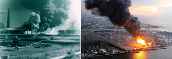
Cylindrical steel storage tanks have prevalent applications in different oil refineries, power plants, industries, and other lifeline facilities in storing liquid including water, petrochemicals, liquefied natural gas (LNG), and other hazardous substances. These liquid-filled steel storage tanks are more susceptible to local buckling when experienced by lateral seismic forces [1]. The most common buckling modes observed during past earthquakes are elephant-foot (elastic-plastic), and diamond-shaped (elastic) buckling. Some other failures and damages during past seismic events including roof damage, base-plate connection failure due to overturning (uplift mechanism) moment, pipe connections, failure due to foundation settlement, and soil liquefication are reported in the literature. Failure of these structures containing hazardous substances can cause fire explosion leading to a huge economic loss, human health as well as interruption of the supply chain [2]. Figure 1 illustrates the buckling behavior of cylindrical steel storage tanks subjected to seismic excitations [3].
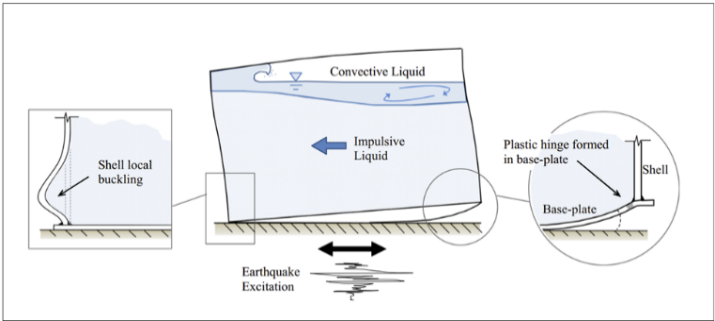
This shell instability (buckling) in cylindrical steel storage tanks is mainly caused by large axial compressive stresses on the tank wall induced by hydrodynamic impulsive force near the tank base. This complex problem of fluid-structure interaction needs a better understanding for capturing the actual response of cylindrical steel tanks subjected to seismic loadings. Most of the design code provisions are unable to evaluate this complex nature and hence it is beyond their scope. This paper investigates the seismic nonlinear behavior of a liquid-filled steel storage tank and the effects of FSI are evaluated using a coupled-acoustic structure interaction (CAS) approach.
2. Literature Review
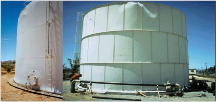
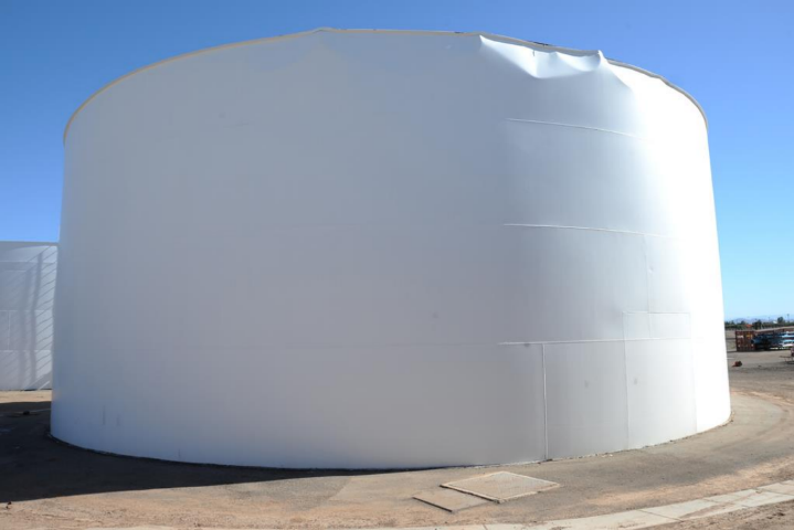
For the last 25 years, there have been sever earthquake that caused catastrophic damage to liquid-filled storage tanks. In the past seismic events such as the 1964 Niigata earthquake, the Tokohu 2011 earthquake in Japan, the 1960 Chilean earthquake, the 1992 earthquake in Landers as well as 2010 Calexico earthquake in California, many storage tanks were damaged because of the poor seismic design. Figures 2 through 4 show the damage of different storage tanks in oil refineries, power plants, and other water reservoirs during past earthquakes [9].
Many researchers have contributed their efforts in understanding the dynamic behavior and the effects of fluid-structure interaction (FSI) under seismic excitations. Sezen et al. [4] investigated the dynamic behavior and seismic performance evaluation of liquid-containing tanks. The authors investigated the different parameters affecting the dynamic behavior of the tanks. Alireza and Shervin [5] evaluated the buckling behavior using finite element analysis (FEA) of three storage tanks with different aspect ratios. The authors concluded that the slender tanks were more vulnerable to buckling instability.
Miguel et al. [6] performed experimental analysis on flexible storage tanks and the effects of liquids on storage tanks under seismic excitation was presented. Some other researchers also investigated the seismic behavior of both flexible and base-restrained storage tanks [7]. The authors used an added-mass approach to evaluate the FSI using FEA, and various buckling modes were investigated. It was concluded that the flexible models were more vulnerable to secondary buckling and only a few tanks were experienced with diamond-shaped buckling. Rebouillat and Liksonov [8] presented numerical approaches for investigating the FSI in partially liquid-filled storage tanks subjected to lateral seismic forces. The liquid-sloshing wave height, frequency, and distribution of the hydrodynamic pressure were evaluated. The results were compared with both experimental and theoretical solutions. In recent years some other researchers evaluated the seismic behavior and the effects of FSI in horizontal liquid-containing tanks using a combined smooth-particle hydrodynamic (SPH-FEM) coupling approach. The findings revealed that the horizontal liquid-filled tanks have significant seismic performance and remain safe without significant damage.
Despite the above contribution in this field, there are still some challenges in evaluating the seismic nonlinear behavior of cylindrical storage tanks using more advanced computation techniques. The seismic behavior of different liquid-filled storage tanks under both horizontal and vertical seismic excitations needs to be investigated. Most of the code provisions do not consider the effects of vertical seismic excitations. This research presents the seismic nonlinear behavior of a liquid-filled steel storage tank considering FSI using the CAS modeling approach. The time history response, deformation response, hoop stresses, and the distribution of maximum stresses are evaluated.
3. Finite Element Modeling
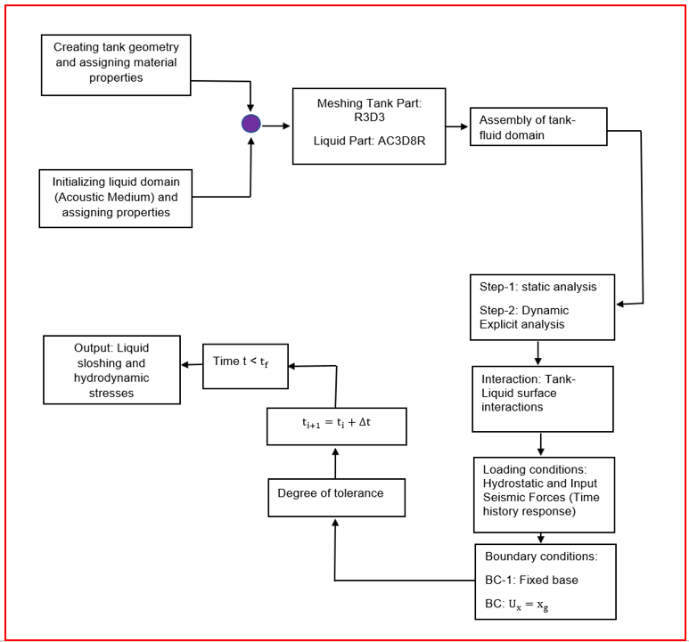
FEM is a powerful tool that can be used for different applications in the field of structural engineering, earthquake engineering, or any other engineering field. In this study, Finite element analysis (FEA) using commercial software ABAQUS is conducted to evaluate the buckling response of cylindrical steel tanks. Initially, to substantiate the accuracy of the FEA, an experimentally tested specimen [10] is considered for buckling analysis and the results are compared with the actual test as well as theoretical solutions. Furthermore, based on this study a parametric analysis of a liquid-filled cylindrical steel storage tank subjected to seismic excitation is conducted and the seismic response under two real-world earthquakes is evaluated. The fluid-structure interaction of the liquid-filled storage tanks is evaluated using the Coupled Acoustic-Structure (CAS) approach as illustrated in Figure 5.
A cylindrical steel shell is being analyzed using Finite Element (FE) analysis, considering the following geometric and material properties: height = 1250 mm, radius R = 500 mm, and plate thickness t = 1.00 mm. The material’s modulus of elasticity E is 210 GPa, and Poisson's ratio ν is 0.29. An external uniform pressure is applied to the cylindrical specimen. The specimen is subjected to simply supported boundary conditions at the top and bottom of the cylindrical shell, as illustrated in Figure 6.
Different mesh sizes (25 mm, 20 mm, and 14 mm) are investigated to assess their impact on the buckling load. A mesh sensitivity study reveals that a 14 mm mesh size using S4R elements (as shown in Figure 7) yields more reasonable results compared to both experimental and theoretical solutions.
3.1 Results and Discussion
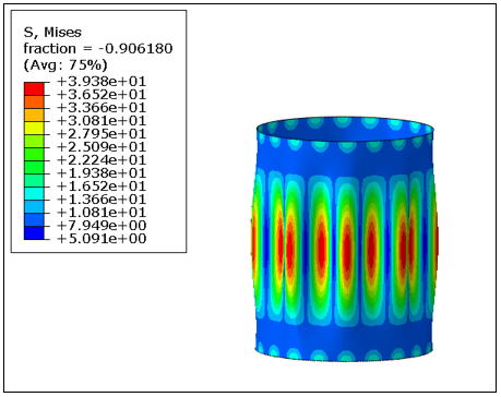
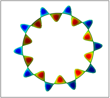
The buckling behavior of a cylindrical steel specimen was evaluated, focusing on its deformation response and the distribution of von Mises stresses. Figures 8(a) and (b) illustrate the specimen's deformation response and stress distribution, respectively, under external uniform pressure.
(a)
(b)
Observations reveal that both the deformation and stresses are most concentrated at the center of the cylindrical shell, decreasing towards the supported edges. The number of waves obtained from Finite Element Analysis (FEA) is compared with those predicted by theoretical Equation [10]. This equation calculates the total number of waves as follows:
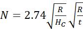
Here, R represents the shell thickness, hc denotes the cylinder height, and t indicates the plate thickness. The buckling pressure obtained from Finite Element Analysis (FEA) is compared with values obtained from theoretical equations 2 and 3 [11-12].
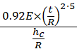
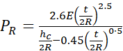
Here, E represents the modulus of elasticity, t denotes the shell thickness, and R and hc denote the radius and height of the cylindrical shell, respectively. The results are summarized in Table 1.
Table 1: Comparisons of buckling pressure
|
Specimen |
Buckling pressure (Mpa) |
|
|
Perfect specimen |
Experiments |
0.0184 |
|
FEA (present study) |
0.0204 |
|
|
Jawad theory |
0.0136 |
|
|
Ross theory |
0.0137 |
|
The buckling pressure obtained from FEA closely matches both experimental and theoretical solutions. It is noted, however, that FE predicts a slightly higher buckling pressure compared to both test and theoretical results. This discrepancy in buckling pressure can be attributed to the idealized nature of the cylindrical specimen used in the FE model. Similarly, the number of waves obtained from FEA is compared with theoretical predictions. Figure 9 shows FE predicts 10 waves, whereas the equation predicts a total of 8 waves.
4. Parametric Study
In this study, liquid-filled cylindrical steel tank is considered for seismic nonlinear analysis subjected to Friuli and Northridge earthquake. The thickness of the cylindrical shell is provided based on the minimum requirements of the American Petroleum Institution (API-650) corresponding to height, and radius. Table 2 shows the geometry and material characteristics of the storage tank considered for analysis.
Table 2: Geometric and material specifications
|
Geometric description |
Material description |
||||
|
H (m) |
D (m) |
t (m) |
HL (m) |
E(GPa) |
v |
|
9.60 |
20 |
0.01 |
8.00 |
210 |
0.29 |
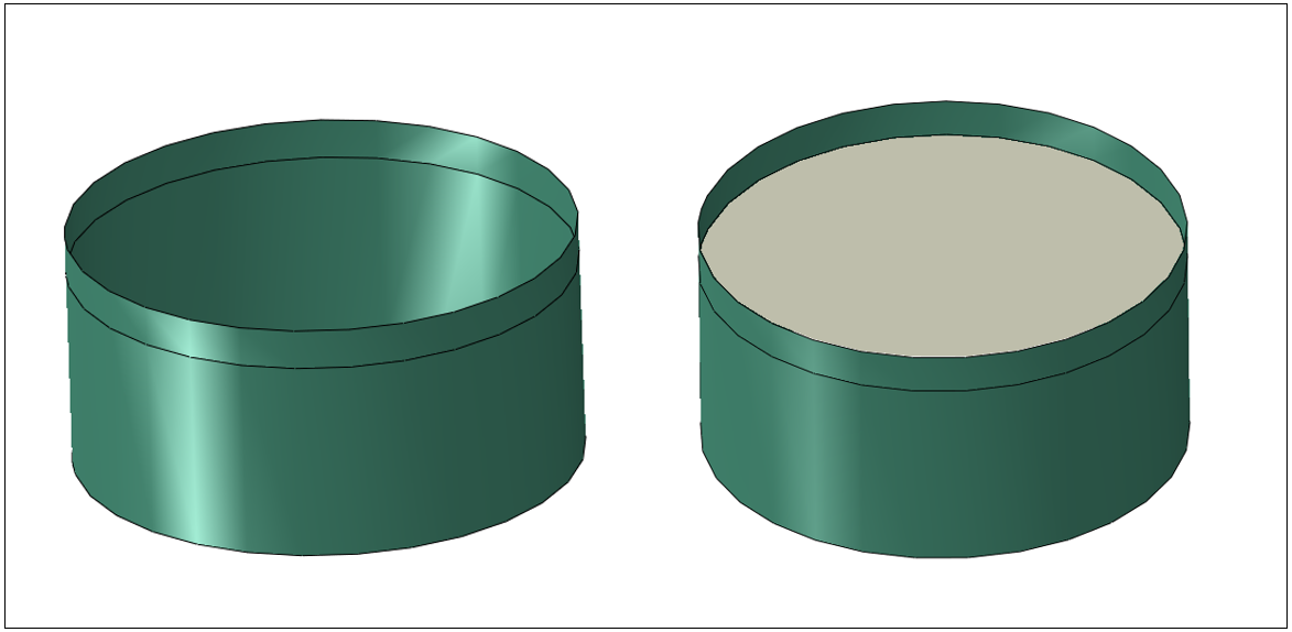
In Table 2, the parameters H, D, t, and HL represent the tank height, diameter, thickness, and liquid-filled level respectively. E and v represent the modulus of elasticity, and poison’s ratio respectively. The assembly of an empty tank for gravity load and hydrostatic nonlinear analysis, and a liquid-filled storage tank for dynamic implicit analysis is illustrated in Figure 10(a) and (b) respectively.
(a) (b)
3.2 Loading, BCs, and 3D Meshing
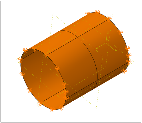
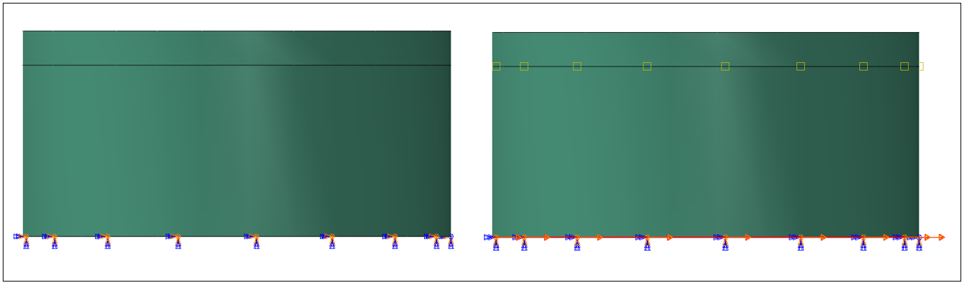
To evaluate the response of the liquid-filled steel storage tank, the load is applied in 3 steps including gravity load (step-1), hydrostatic nonlinear (step-2), and dynamic earthquake loading (dynamic implicit step-3). Initially, the loads in step-1 and step-2 are applied for one second each, and then in step-3 the seismic excitations in BCs at the base are applied for 20 seconds (Friuli 1976 earthquake) and 30 seconds (Northridge 1994 earthquake) respectively. For initial steps of fixed displacement/rotation, BCs are applied as shown in Figure 11(a), and for seismic excitation fixed acceleration/angular acceleration, BCs are applied at the base except for free motion in the horizontal direction as illustrated in Figure 11(b).
(a) (b)
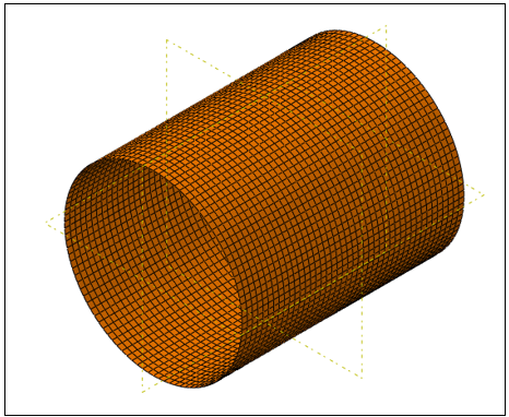
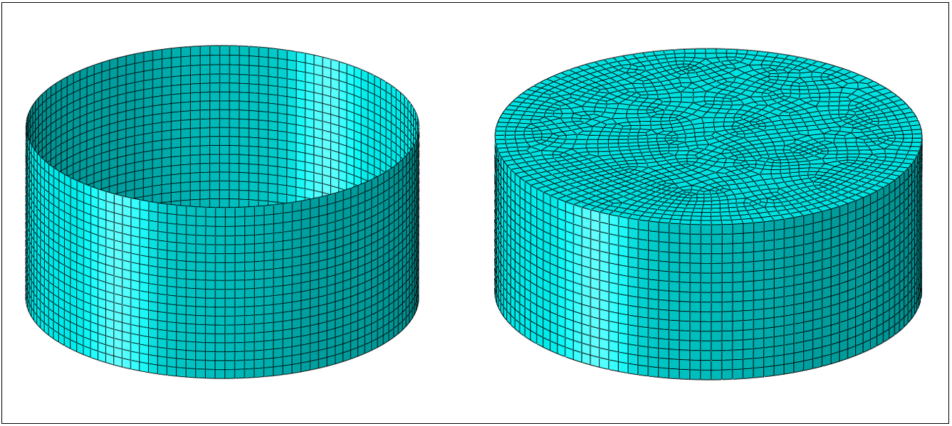
The cylindrical steel shells are modeled using the S4R element Figure 12(a), doubly curved thin shell, reduced integration, and hourglass control. This element has 4 nodes and six degrees of freedom (DoF), 3 translations in nodal x, y, and z directions, and 3 rotational in x, y, and z directions at each node. The liquid domain is modeled as an acoustic medium and the AC3D8R acoustic element having 8 modes is considered for 3D meshing as shown in Figure 12(b).
(a) (b)
Results and Discussion
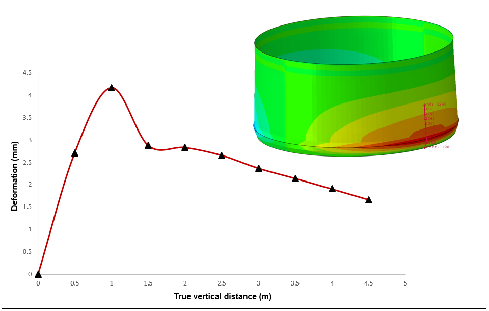
As discussed earlier, the analysis is carried out in 3 steps including gravity load, hydrostatic nonlinear (steps 1 &2), and dynamic implicit analysis in step-3. Figure 13(a) and (b) illustrate the deformation response of the tank subjected to hydrostatic loading. Similarly, the maximum deformation experienced by the tank under hydrostatic load is shown in Figure 14. The tank experiences a maximum of 4.18 mm deformation near the base of the tank.
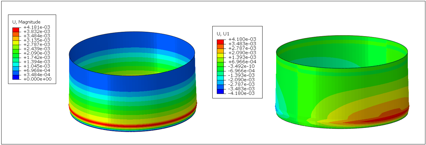
(a) (b)
Furthermore, the maximum von-mises, and hoop (circumferential) stresses are illustrated in Figure 15(a) and (b) respectively. The stress concentration is located at the bottom indicating that critical region and excessive axial stresses can lead the tank to local instability.
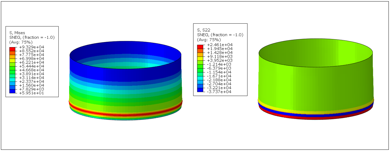
(a) (b)
Nonlinear seismic analysis
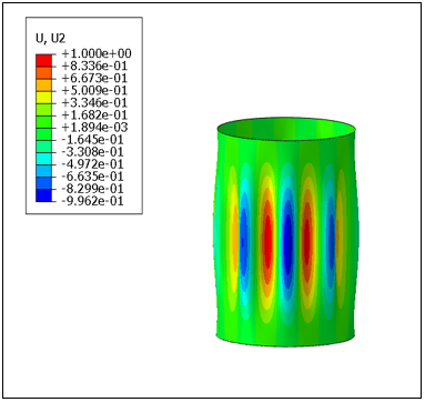
Seismic non-linear analysis of cylindrical liquid-filled steel storage tanks is a crucial step for evaluating the tank's seismic behavior and its performance under seismic loading. This analysis includes assessing the interaction between the fluid and tank (FSI) and its effects on the tank wall. The overall deformation response and the deformation in the horizontal direction of the liquid-filled tank subjected to both Friuli and Northridge seismic loading are shown in Figure 16(a) and (b) and through Figure 17(a) and (b) respectively.
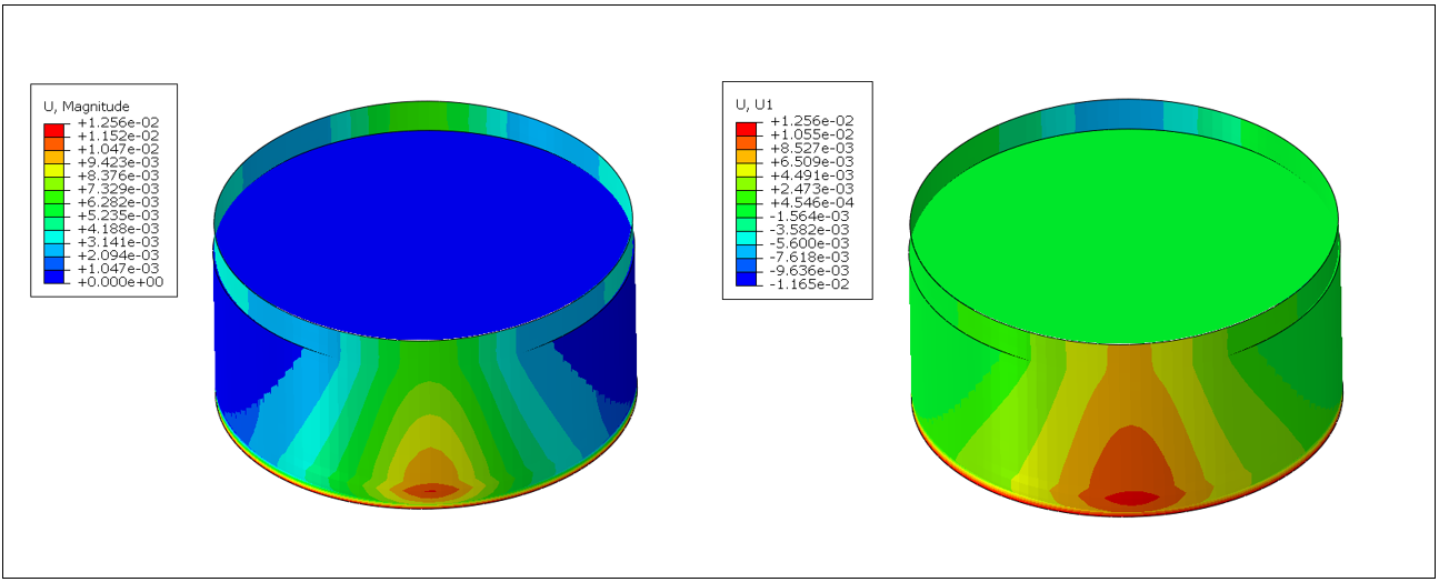
(a) (b)
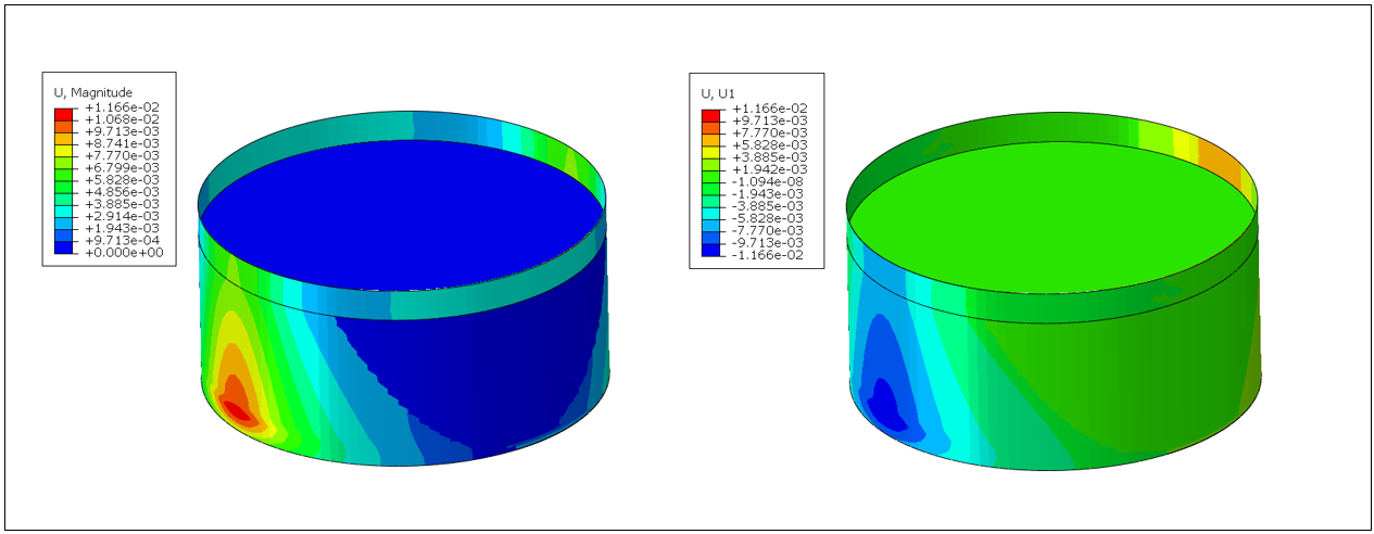
(a) (b)
The analysis reveals that the tank subjected to the Friuli 1974 earthquake experienced slightly higher deformation (7.2% variance) compared to the tank under the Northridge earthquake. Additionally, the maximum and longitudinal stresses experienced by the tank subjected to the Friuli earthquake are 92.0 MPa and 82.0 MPa, respectively. The distribution of von Mises and longitudinal stresses is illustrated in Figure 18(a) and (b), and Figure 19(a) and (b), respectively.
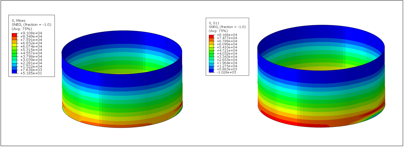
(a) (b)
(a) (b)
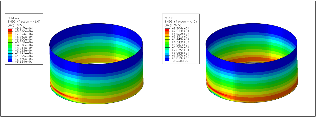
For the tank subjected to Northridge seismic excitation, the maximum and longitudinal stresses are 91.50 MPa and 82.04 MPa, respectively. It can be concluded that there is no significant change in either the maximum von Mises stress or longitudinal stresses when subjected to two different seismic excitations. In both cases, stress concentration occurs at the lower portion of the tank. The distribution of the circumferential (hoop) stresses are shown in Figure 20(a) and (b) respectively. The results indicate that the hoop stresses in tank model subjected to Northridge is slightly higher than the stresses developed in tank model under Friuli seismic excitation.
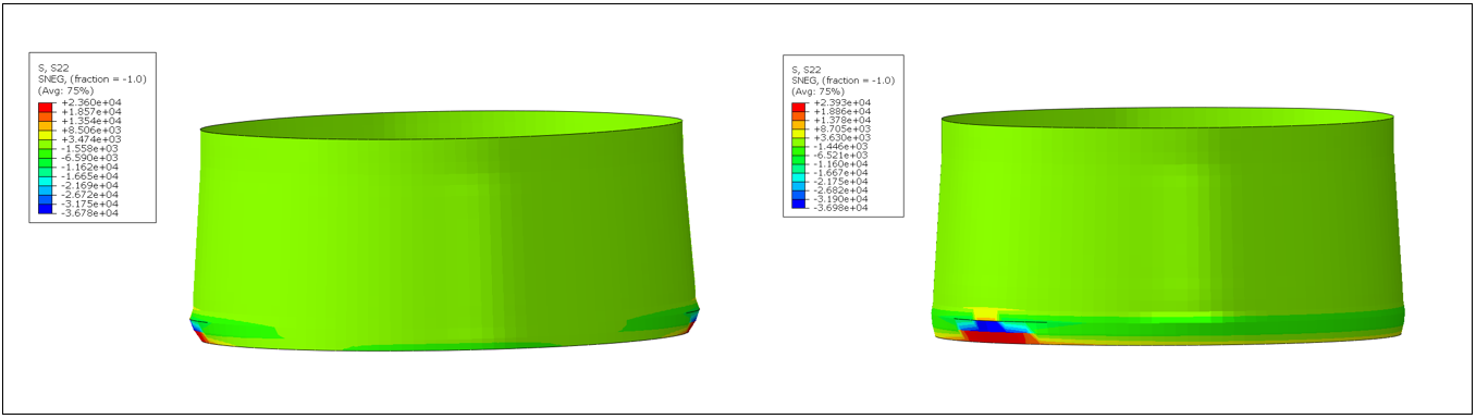
(a) (b)
To evaluate the seismic response of the liquid-filled tank under two different seismic excitations, the maximum response acceleration and the pressure response at the tank wall are estimated. Figure 21(a) and (b) represent the maximum response acceleration components under the seismic excitations (Friuli and Northridge earthquake).
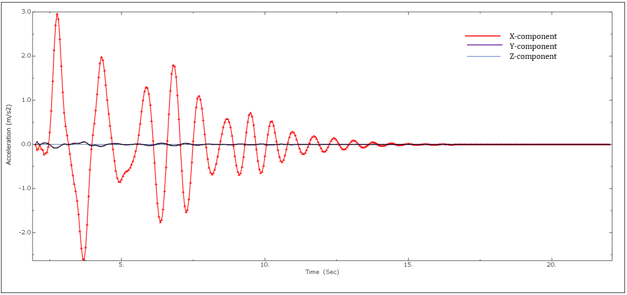
(a)
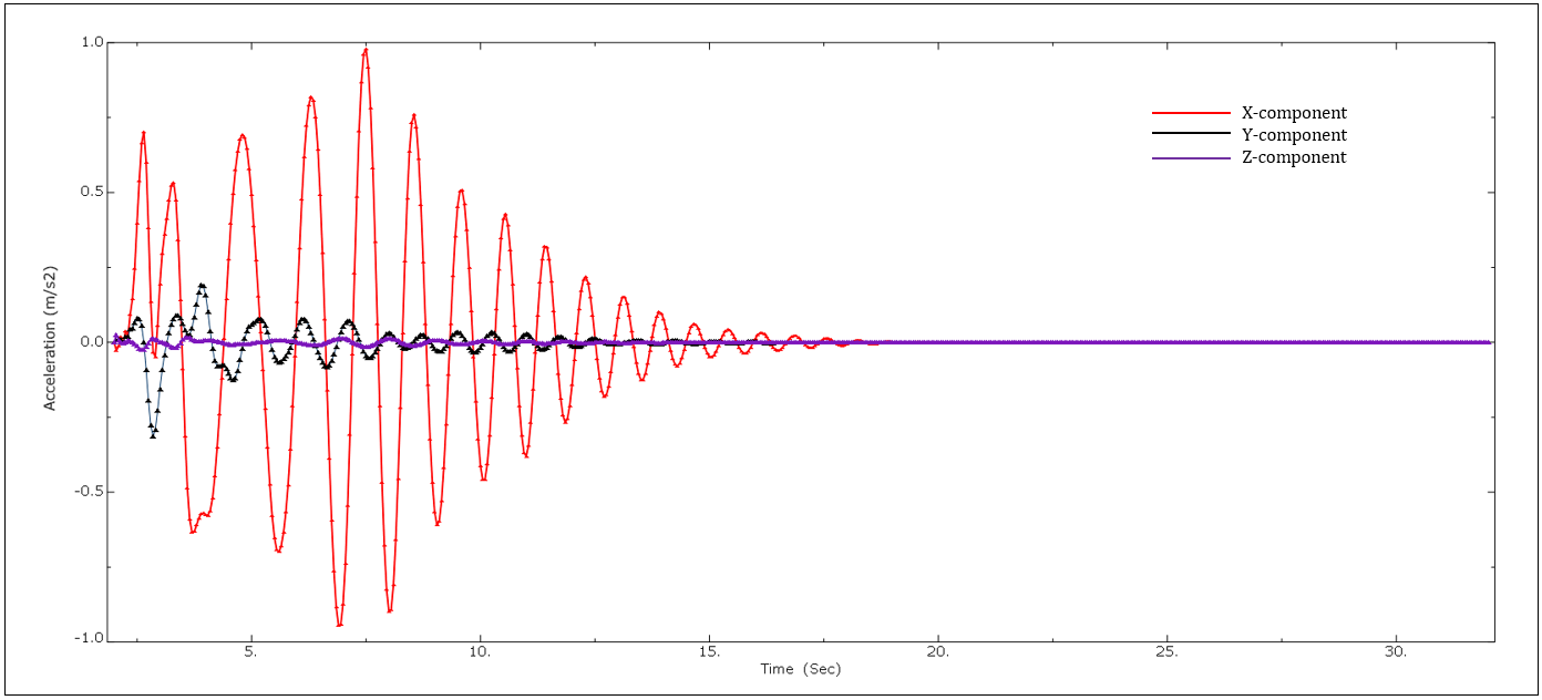
(b)
The acceleration response of the tank subjected to the Friuli earthquake is slightly higher than the response of the tank under the Northridge earthquake. Furthermore, the response shows that maximum excitation is in the lateral direction (x-component) where the ground motion is applied at the storage tank's base. The other components (y and z-components) do not significantly affect the tank's seismic performance. It can also be seen that the response in Z-direction is almost negligible. In the case of the Northridge input excitation, the x-component represents the maximum response of the tank, and the remaining components (y and z-components) do not have a significant contribution to the tank excitations. It can be concluded that the y-component still contributes to the overall tank excitations that can affect the seismic performance when subjected to high seismic events. Therefore, to ensure the safety of the liquid-filled storage tanks under strong seismic events, the vertical excitations must be considered in the seismic design code provisions.
Similarly, the maximum pressure response concerning time is also evaluated under both input seismic excitations. These pressures arise from the interaction between the liquid inside the tank and the inner steel tank walls. When subjected to seismic forces, these pressures generate lateral moments, resulting in hydrodynamic pressure that may contribute to the overturning moment of the storage tanks. The response shown in Figure 22(a) and (b) illustrates that the tank under Friuli seismic excitation has a maximum peak compared to the tank subjected to the Northridge earthquake.
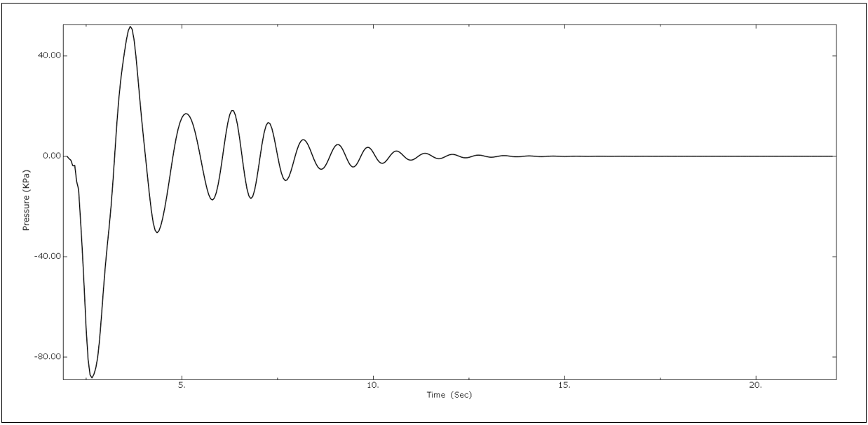
(a)
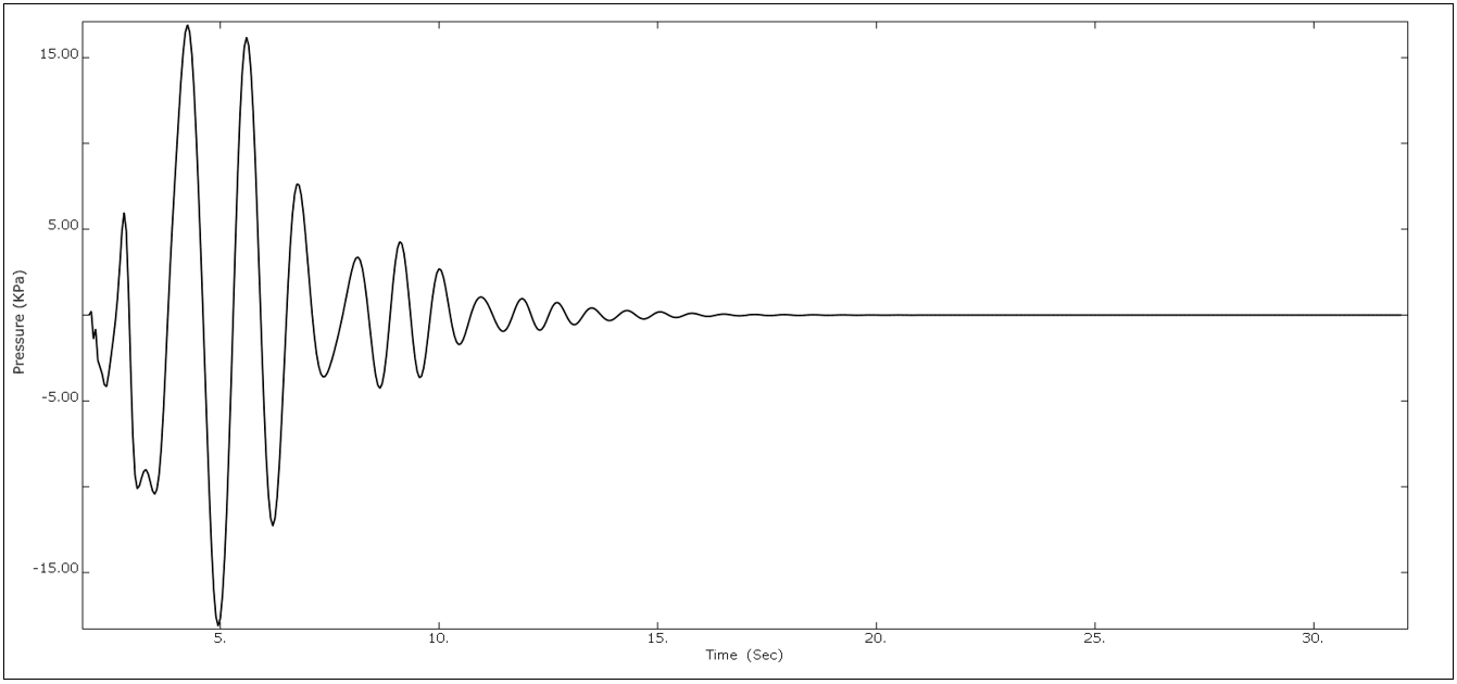
(b)
5. Conclusion
This study presents linear buckling analysis and nonlinear seismic analysis of both an empty steel shell and a liquid-filled steel storage tank (83.4% full) using the finite element analysis (FEA) software ABAQUS. Initially, a perfect specimen is considered for linear buckling analysis, and the results are compared with experimental and theoretical solutions. Secondly, in the parametric study, the cylindrical tank is subjected to seismic excitation in the horizontal direction using two real-world ground motions: the Friuli 1974 and Northridge 1994 earthquakes. The analysis applies loading in three steps: gravity, hydrostatic, and dynamic earthquake loading.
The first two steps, gravity, and hydrostatic loadings, each last for 1 second and account for large deformations (nonlinear behavior). In the third step, dynamic implicit analysis considers periods of 20 and 30 seconds for both seismic excitation cases. The study evaluates deformation response, stress distribution (longitudinal and circumferential), acceleration response, and maximum pressure response.
Based on the analysis, the following conclusions have been drawn:
- For linear buckling analysis, the buckling pressure obtained from FEA closely matches (9.8% variance) the test results and is slightly higher than theoretical predictions. This difference in buckling pressure is primarily due to the idealized nature of the cylindrical specimen considered in FEA.
- Additionally, FEA predicts 10 waves, whereas the theoretical equation estimates 8 waves in a cylindrical steel shell subjected to external uniform pressure.
- Stress concentration is predominantly located at the bottom, indicating a critical region where excessive axial stresses could potentially induce local instability in the tank.
- Nonlinear response analysis reveals that the tank subjected to the Friuli 1974 earthquake experienced slightly higher deformation (7.2% variance) compared to the tank under the Northridge earthquake.
- There is no significant difference observed in both the maximum von Mises stress and longitudinal stresses when the tank is subjected to the two different seismic excitations. Stress concentration occurs consistently at the lower portion of the tank model in both cases.
- The maximum and longitudinal stresses experienced by the tank subjected to the Friuli earthquake are 92.0 MPa and 82.0 MPa, respectively.
- For the tank subjected to Northridge seismic excitation, the maximum and longitudinal stresses are 91.50 MPa and 82.04 MPa, respectively.
- Results indicate that the hoop stresses in the tank model subjected to the Northridge earthquake are slightly higher than those developed in the tank model under the Friuli seismic excitation.
- The maximum hoop stresses of the tank under the Friuli and Northridge earthquakes are 23.60 Mpa and 23.93 Mpa, respectively.
- Acceleration response analysis shows that the tank subjected to the Friuli earthquake experiences slightly higher excitation than the tank under the Northridge earthquake. Maximum excitation is observed in the lateral direction (x-component) where the ground motion is applied at the tank base, while the y and z-components do not significantly affect the seismic performance of the tank.
- Under Northridge seismic excitation, the x-component exhibits the maximum tank response, while the y and z-components contribute less to the overall tank excitation. However, the y-component does affect the tank's seismic performance during strong seismic events. Therefore, seismic design code provisions should consider vertical excitations to ensure the safety of liquid-filled storage tanks.
References
[1] S. Ullah, and I.H.P Mamaghani. “Numerical Investigation on Buckling Response of Cylindrical Steel Storage Tanks Under Static Loading” " in Proceedings of the 9th International Conference on Civil, structural and Transportation Engineering, 2024.
View Article
[2] S. Ullah, and I.H.P Mamaghani. "Numerical Investigation on Buckling Response of Cylindrical Steel Storage Tanks Under Seismic Excitation." 2nd Conference of the European Association on Quality Control of Bridges and Structures (2023): 343-347.
View Article
[3] G. Cortes, and P. Gary. "Seismic fragility analysis of large unanchored steel tanks considering local instability and fatigue damage." Bulletin of Earthquake Engineering 15 (2017): 1279-1295.
View Article
[4] H. Sezen, L. Ramazan, and D. Adem, "Dynamic analysis and seismic performance evaluation of above-ground liquid-containing tanks." Engineering Structures 30.3 (2008): 794-803.
View Article
[5] M. Mehretehran, and M. Shervin. "3D buckling assessment of cylindrical steel silos of uniform thickness under seismic action." Thin-Walled Structures 131 (2018): 654-667.
View Article
[6] M. Ormeño, L. Tam, and C. Nawawi. "Experimental study of the effect of a flexible base on the seismic response of a liquid storage tank." Thin-Walled Structures 139 (2019): 334-346.
[7] K. Kildashti, M. Neda, and S. Bijan. "Seismic vulnerability assessment of a case study anchored liquid storage tank by considering fixed and flexible base restraints." Thin-Walled Structures 123 (2018): 382-394.
View Article
[8] S. Rebouillat, and D. Liksonov. "Fluid–structure interaction in partially filled liquid containers: a comparative review of numerical approaches." Computers & Fluids 39.5 (2010): 739-746.
View Article
[9] I. Bahreini. “Experimental and Numerical Investigation of Liquid Storage Tanks Under Seismic Excitation”. MS Dissertation, Dept. Civil Eng., University of Ottawa, OT, 2016.
View Article
[10] K. F. M Aydin, M. Maali, M. Kilic, and A. C Aydin "Experimental analysis of the effect of dent variation on the buckling capacity of thin-walled cylindrical shells." Thin-walled structures 143 (2019): 106259.
View Article
[11] M.H Jawad. “Theory and Design of Plate and Shell Structures”, Chapman & Hall, 1994.
[12] C.T.F Ross “A proposed design chart to predict the inelastic buckling pressures for conical shells under uniform external pressure”, Mar. Technol. 44 (2) (2007) 77–81.
View Article
[1] S. Ullah, and I.H.P Mamaghani. “Numerical Investigation on Buckling Response of Cylindrical Steel Storage Tanks Under Static Loading” " in Proceedings of the 9th International Conference on Civil, structural and Transportation Engineering, 2024. View Article
[2] S. Ullah, and I.H.P Mamaghani. "Numerical Investigation on Buckling Response of Cylindrical Steel Storage Tanks Under Seismic Excitation." 2nd Conference of the European Association on Quality Control of Bridges and Structures (2023): 343-347. View Article
[3] G. Cortes, and P. Gary. "Seismic fragility analysis of large unanchored steel tanks considering local instability and fatigue damage." Bulletin of Earthquake Engineering 15 (2017): 1279-1295. View Article
[4] H. Sezen, L. Ramazan, and D. Adem, "Dynamic analysis and seismic performance evaluation of above-ground liquid-containing tanks." Engineering Structures 30.3 (2008): 794-803. View Article
[5] M. Mehretehran, and M. Shervin. "3D buckling assessment of cylindrical steel silos of uniform thickness under seismic action." Thin-Walled Structures 131 (2018): 654-667. View Article
[6] M. Ormeño, L. Tam, and C. Nawawi. "Experimental study of the effect of a flexible base on the seismic response of a liquid storage tank." Thin-Walled Structures 139 (2019): 334-346.
[7] K. Kildashti, M. Neda, and S. Bijan. "Seismic vulnerability assessment of a case study anchored liquid storage tank by considering fixed and flexible base restraints." Thin-Walled Structures 123 (2018): 382-394. View Article
[8] S. Rebouillat, and D. Liksonov. "Fluid–structure interaction in partially filled liquid containers: a comparative review of numerical approaches." Computers & Fluids 39.5 (2010): 739-746. View Article
[9] I. Bahreini. “Experimental and Numerical Investigation of Liquid Storage Tanks Under Seismic Excitation”. MS Dissertation, Dept. Civil Eng., University of Ottawa, OT, 2016. View Article
[10] K. F. M Aydin, M. Maali, M. Kilic, and A. C Aydin "Experimental analysis of the effect of dent variation on the buckling capacity of thin-walled cylindrical shells." Thin-walled structures 143 (2019): 106259. View Article
[11] M.H Jawad. “Theory and Design of Plate and Shell Structures”, Chapman & Hall, 1994.
[12] C.T.F Ross “A proposed design chart to predict the inelastic buckling pressures for conical shells under uniform external pressure”, Mar. Technol. 44 (2) (2007) 77–81. View Article